Phase adjustment circuit
A phase adjustment and circuit technology, which is applied to electrical components, generation/distribution signals, automatic power control, etc., can solve problems such as unstable judgment, and achieve the effect of suppressing dispersion and not changing the phase position
- Summary
- Abstract
- Description
- Claims
- Application Information
AI Technical Summary
Problems solved by technology
Method used
Image
Examples
Embodiment approach 1
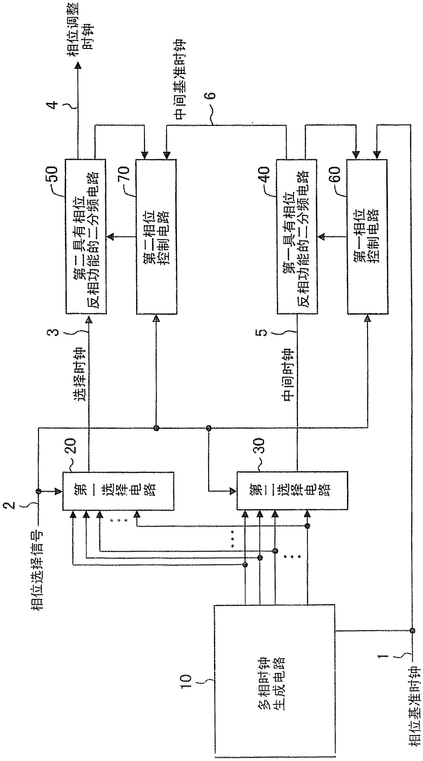
[0047] figure 1 The configuration of the phase adjustment circuit in Embodiment 1 of the present invention is shown.
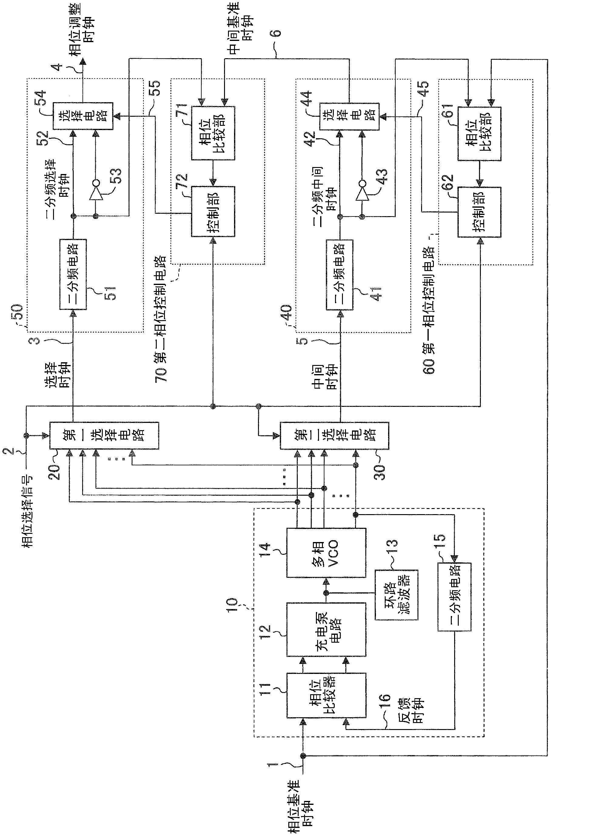
[0048] exist figure 1 Among them, the phase adjustment circuit in Embodiment 1 is composed of the following parts: a multi-phase clock generation circuit 10 that generates a multi-phase clock that is twice the frequency of the phase reference clock 1; and selects one of the multi-phase clocks according to the phase selection signal 2 The first selection circuit 20 that outputs as the selection clock 3; the second selection circuit 30 that selects the clock that is separated from the phase reference clock 1 and the selection clock 3 from the multi-phase clock and outputs it as the intermediate clock 5; The intermediate clock is divided by two and output as the intermediate reference clock 6. The first divide-by-two circuit 40 with phase inversion function; The two frequency division circuit 50 of inversion function; Control generates the output phase of the f...
Embodiment approach 2
[0071] Hereinafter, the phase adjustment circuit in Embodiment 2 of the present invention will be described with reference to the drawings. In addition, in this embodiment, the same code|symbol is attached|subjected to the same part as Embodiment 1, and the detailed description is abbreviate|omitted.
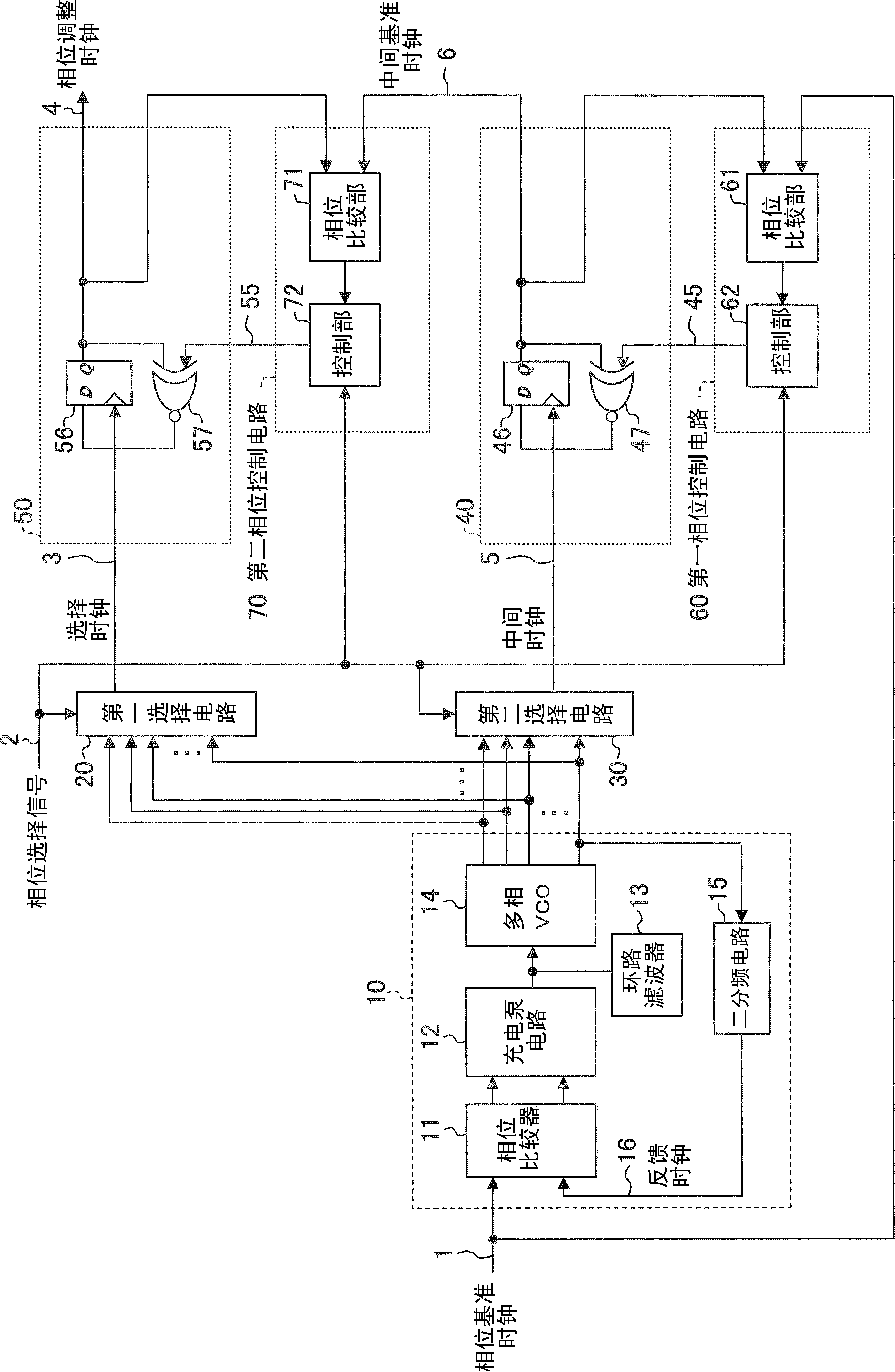
[0072] image 3 The circuit structure of the phase adjustment circuit of Embodiment 2 is shown. The difference between this embodiment and Embodiment 1 lies in that the structures of the first and second frequency-dividing-by-two circuits with phase inversion function and the first and second phase control circuits are different.
[0073] exist image 3 Among them, the first frequency division circuit 40 with phase inversion function is composed of the following parts: the intermediate clock 5 is used as the clock signal, and its output is output as the D-type flip-flop 46 of the intermediate reference clock 6; and the The output of the D-type flip-flop 46 and the inverted co...
Embodiment approach 3
[0082] Hereinafter, the phase adjustment circuit in Embodiment 3 of the present invention will be described with reference to the drawings. In addition, in this embodiment, the same code|symbol is attached|subjected to the same part as Embodiment 1, and detailed description is abbreviate|omitted.
[0083] Figure 4 It is a circuit configuration diagram of a phase adjustment circuit according to Embodiment 3. This embodiment differs from Embodiment 1 in that the structure of the second phase control circuit 70 is different.
[0084] exist Figure 4 Among them, the second phase control circuit 70 is composed of the following parts: the second frequency division circuit 73 that divides the selection clock 3 by two and outputs the second frequency division selection clock 74; performs the intermediate reference clock 6 and the second division clock The phase comparison section 71 of the phase comparison of the frequency selection clock 74; and the control section 72, which cont...
PUM
 Abstract
Description
Claims
Application Information
 - R&D
- Intellectual Property
- Life Sciences
- Materials
- Tech Scout
- Unparalleled Data Quality
- Higher Quality Content
- 60% Fewer Hallucinations
Browse by: Latest US Patents, China's latest patents, Technical Efficacy Thesaurus, Application Domain, Technology Topic, Popular Technical Reports.
© 2025 PatSnap. All rights reserved.Legal|Privacy policy|Modern Slavery Act Transparency Statement|Sitemap|About US| Contact US: help@patsnap.com


