A wide frequency continuously adjustable pulse width wave digital generation method and system

A technology of pulse width and frequency, which is applied in the field of continuously adjustable pulse width wave digital generation method and system, can solve the problems of low pulse width wave quality, waveform edge jitter, etc., and achieve improved phase resolution, zero edge jitter, The effect of improving accuracy

Active Publication Date: 2016-10-26
UNI TREND TECH (CHINA) CO LTD
View PDF5 Cites 0 Cited by
  • Summary
  • Abstract
  • Description
  • Claims
  • Application Information

AI Technical Summary

Problems solved by technology

[0003] In view of this, this application provides a pulse width wave digital generation method and system with continuously adjustable frequency, which is used to solve the pulse width wave generated by existing means, and there will be waveform edge jitter when the frequency is high. Generated pulse width waves are of low quality

Method used


Image

  • A wide frequency continuously adjustable pulse width wave digital generation method and system
  • A wide frequency continuously adjustable pulse width wave digital generation method and system
  • A wide frequency continuously adjustable pulse width wave digital generation method and system

Examples


Embodiment 1

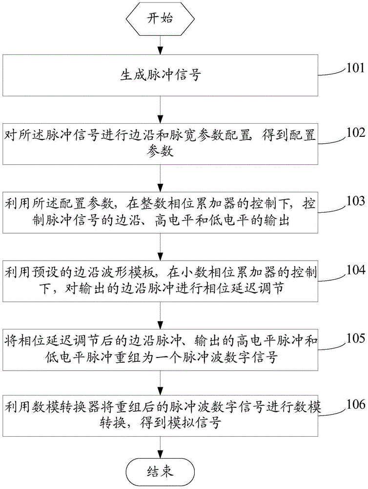
[0045] see figure 1 , figure 1 It is a flow chart of a method for digitally generating pulse width waves with continuously adjustable frequency, which is disclosed in the embodiment of this application.

[0046] Such as figure 1 As shown, the method includes:

[0047] Step 101: generating a pulse signal;

[0048] Specifically, a pulse signal can be generated by a pulse transmitter for subsequent use.

[0049] Step 102: Configure edge and pulse width parameters of the pulse signal to obtain configuration parameters;

[0050] Specifically, the configuration parameters here include various information such as edge output time of subsequent pulses, high and low level output times, and edge and high and low level output waveforms.

[0051] Step 103: Using the configuration parameters, under the control of the integer phase accumulator, control the output of the edge, high level and low level of the pulse signal;

[0052] Specifically, according to the content of the configura...

Embodiment 2

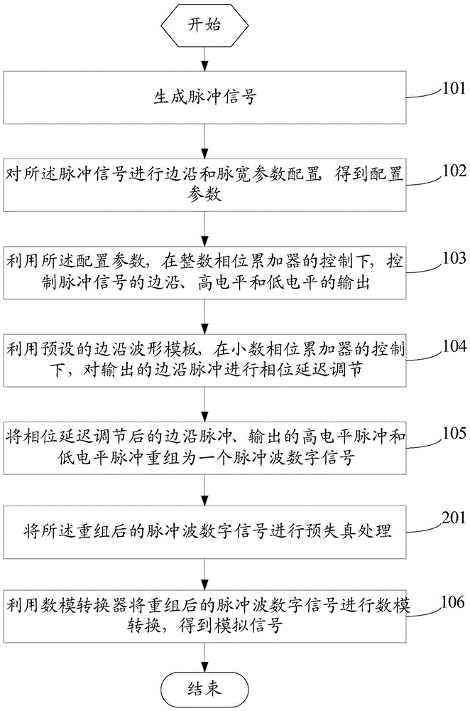
[0063] In the above embodiment, in step 106, the digital-to-analog converter is used to perform digital-to-analog conversion on the recombined pulse wave digital signal to obtain an analog signal. However, when outputting fast-edge signals, the digital-to-analog converter DAC will have additional overshoot. However, in order to realize the wideband adjustable edge, it is unavoidable to generate a very short fast edge signal. To address this issue, we performed the following analysis.

[0064] Since the above-mentioned overshoot phenomenon is determined by the inherent characteristics of the digital-to-analog converter DAC, if the system transfer function of the DAC can be obtained, a feedback loop opposite to the overshoot can be established, so that the input signal before entering the DAC The opposite over-damping distortion occurs, and then the ideal output signal can be obtained through the overshoot compensation of the DAC.

[0065] Therefore, see figure 2 , figure ...

Embodiment 3

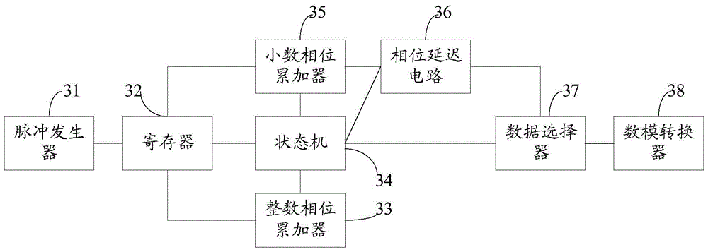
[0073] see image 3 , image 3 It is a structural diagram of a continuously adjustable frequency pulse width wave digital generation system disclosed in the embodiment of this application.

[0074] Such as image 3 As shown, the system includes:

[0075] Pulse generator 31, for generating pulse signal;

[0076] Register 32, configured to store configuration parameters of the edge and pulse width of the pulse signal;

[0077] Specifically, the configuration parameters here are preset, and include various information such as edge output time of subsequent pulses, high and low level output times, and edge and high and low level output waveforms.

[0078] An integer phase accumulator 33 is used to provide a time basis for the output of the pulse signal;

[0079] A state machine 34, configured to use the configuration parameters to control the output of the edge, high level and low level of the pulse signal under the control of the integer phase accumulator;

[0080] Specific...


PUM


Abstract

The invention discloses a method for generating pulse width wave digits with the continuously-adjusted wide frequency. The method comprises the steps of conducting edge and pulse width parameter configuration on produced pulse signals to obtain configuration parameters, then according to the control over the configuration parameters by an integer phase accumulator, controlling the output of the edge, the high level and the low level of pulse signals, and therefore firstly outputting pulse waves from the large angle, then, utilizing a preset edge waveform template, under the control by a decimal phase accumulator, conducting phase delay adjustment on output edge pulses, completely showing time details through fine tuning of the edge phases, improving the phase resolution ratio, enabling the edges of finally output recombined pulse waves to conduct low shaking, finally, conducting digital-to-analogue conversion on processed pulse wave digital signals, and obtaining ultimately-wanted high-quality analog signals.

Description

technical field [0001] The technical field of pulse wave processing of the present application, more specifically, relates to a method and system for digitally generating pulse width waves with continuously adjustable frequency. Background technique [0002] Adjustable pulse width wave is one of the basic waveforms that are widely used. The existing method for generating adjustable pulse width waves is to use a direct digital frequency synthesizer to repeatedly output pre-prepared data in a look-up table under a given digital system working clock. However, when outputting a pulse width wave with an adjustable frequency and a given edge time, if a look-up table is used, the given edge time will also change with the change of the output frequency. When the output frequency is not an integer number of system times, the accumulation of the output time will lead to an error of one system cycle time contained in an adjacent cycle, resulting in jitter on the edge of the waveform, ...

Claims


Application Information

Patent Timeline
Patent Type & Authority Patents(China)
IPC IPC(8): H03K3/02H03M1/66
Inventor 宋大嵩孙乔王量
Owner UNI TREND TECH (CHINA) CO LTD
Why Eureka
Try Eureka