Clamping and conveying device for conveying steel bars

A technology for steel bars and main boxes, applied in the field of pinch devices, can solve the problems of increased maintenance frequency and cost, poor clamping and separation accuracy, and large space occupation in the factory area, so as to reduce maintenance costs and accurately limit positions , the effect of taking up less space

Inactive Publication Date: 2012-01-18
王丽燕
View PDF5 Cites 8 Cited by
  • Summary
  • Abstract
  • Description
  • Claims
  • Application Information

AI Technical Summary

Problems solved by technology

[0002] With the rapid development of my country's economy, the steel rolling industry is also changing with each passing day. In the steel rolling process, the steel bars that have just been rolled need to be cut to the required size, and then placed on the cooling bed for natural cooling. The steel bars need to enter the cooling bed area from the cutting area. The pinch device is used for conveying. The current pinch device structure includes the main box, the auxiliary box, the upper roller, the lower roller and the cylinder. The lower roller is installed on the lower part of the main box, and the upper roller is installed on the auxiliary box. The upper roller and the lower roller are arranged in parallel, and the main and auxiliary boxes adopt self-splash lubrication, which has poor lubricating effect and requires frequent replacement of lubricating oil. , the main box and the auxiliary box are connected in two parts by a hinged bracket, and the main box and the auxiliary box are clamped and separated by the cylinder drive to realize the upper roller and the lower roller to convey the steel bar. This structure has the following disadvantages , because the main box and the auxiliary box are designed separately, the volume is large, and the space in the factory area is occupied. Poor, slow shipping, high cost

Method used


Image

  • Clamping and conveying device for conveying steel bars
  • Clamping and conveying device for conveying steel bars
  • Clamping and conveying device for conveying steel bars

Examples


Embodiment Construction

[0024] The present invention will be further described in detail below through specific examples. The following examples are only descriptive, not restrictive, and cannot limit the protection scope of the present invention.

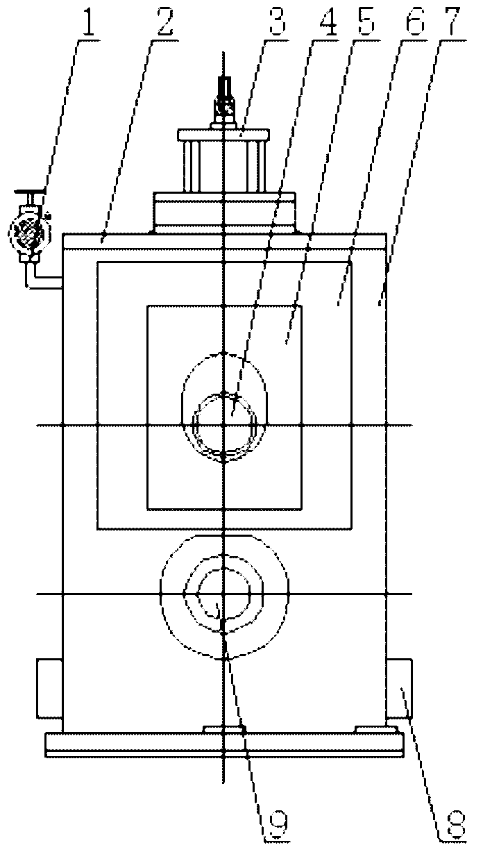
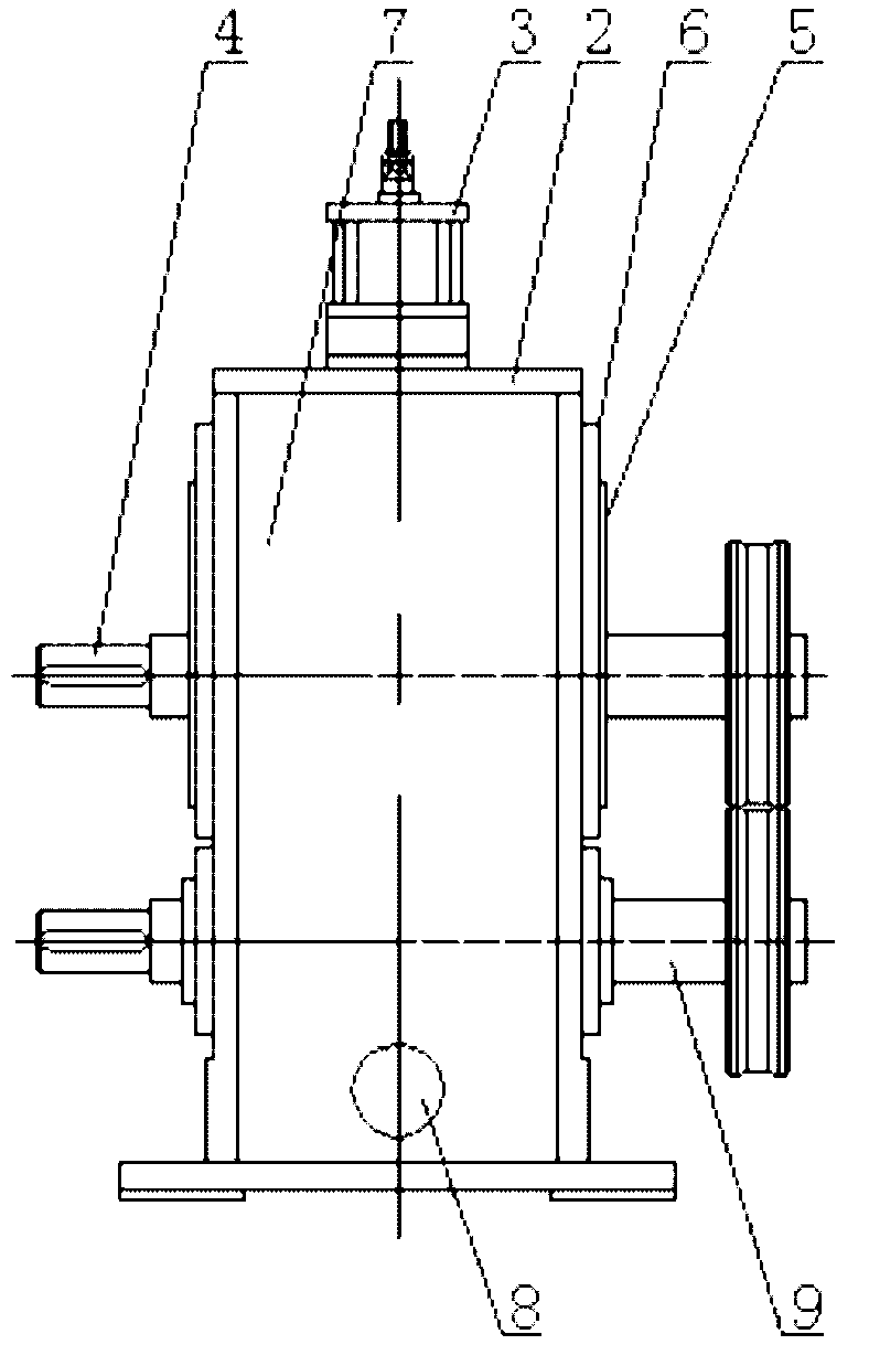
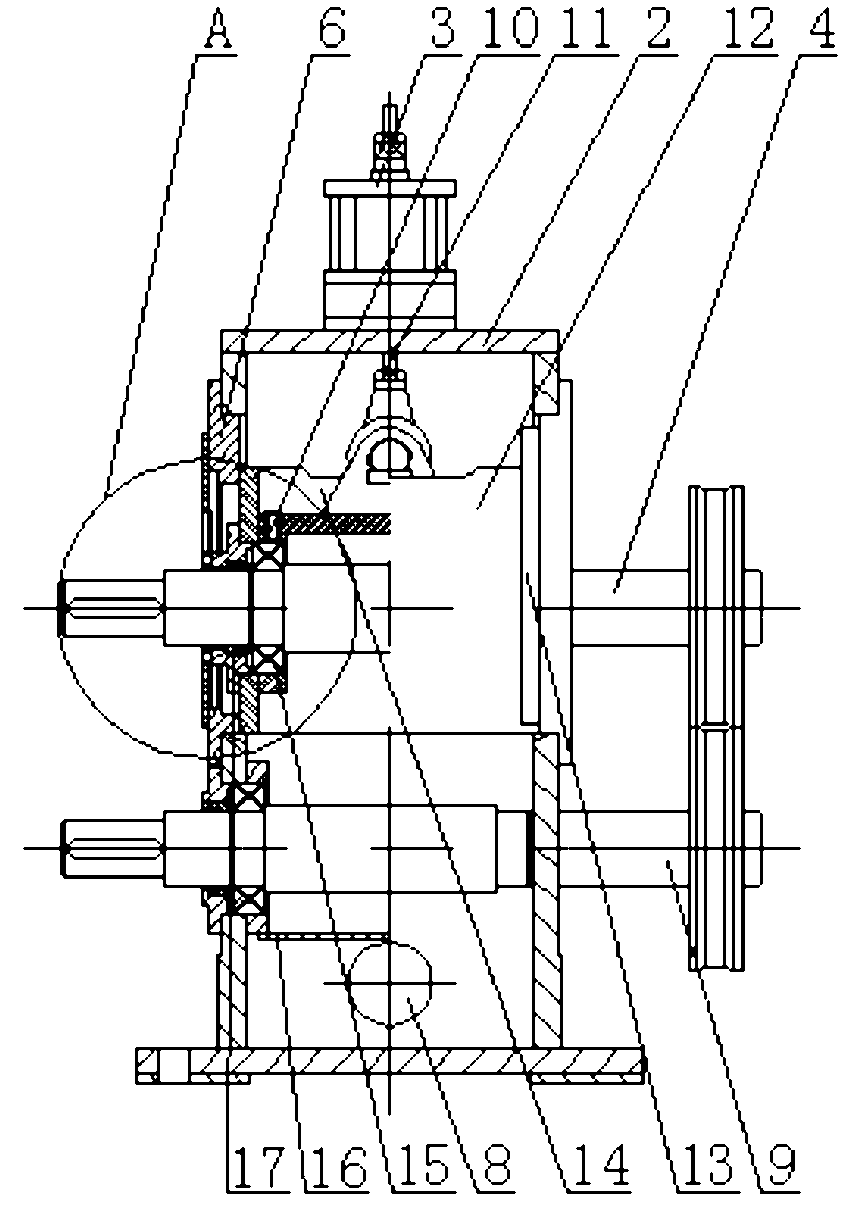
[0025] A pinch device for conveying steel bars, comprising a main box body 7, an auxiliary box body 12, an upper roller 4, a lower roller 9 and an air cylinder 3, and the lower roller is rotatably installed at the lower part of the main box body, as shown in the drawings of this embodiment The lower roller shown in the figure is installed on the main box through bearings and gaskets, the upper roller is rotatably installed on the auxiliary box, the upper roller is installed on the auxiliary box through bearings 15 and gaskets 17, and an oil tank 14 is arranged on the top of the auxiliary box. , an oil supply hole 10 is formed on the auxiliary box above the upper roller, the upper roller and the lower roller are arranged in parallel, the upper part of the m...


PUM


Abstract

The invention relates to a clamping and conveying device for conveying steel bars. The device comprises a main box, a secondary box, an upper roller, a lower roller and a cylinder, wherein the secondary box is glidingly arranged in the main box at the upper part of the lower roller; the secondary box is driven by the cylinder fixedly arranged at the top of the main box; the main box at two ends of the upper roller is provided with symmetrical end covers respectively; each end cover is provided with an upper roller sliding hole and an oil return baffle plate; the lower part of the oil return baffle plate is provided with an oil return oil; an oil baffle cover plate is fixedly arranged at the outer side of the end cover; the oil baffle cover plate is provided with a cover plate through holecorresponding to the upper roller sliding hole; and a dustproof oil baffle cover is fixedly arranged on the upper roller bearing end cover between the oil baffle cover plate and the oil return baffleplate. The device has compact structure, scientific and reasonable design, low manufacturing cost, small volume and high clamping accuracy, and can adapt to the steel bars of different specifications; the lubricating mode is circulating oil reinforced lubrication; and the device is reliable in sealing and high in transport velocity, improves the production efficiency of the steel bars, prolongs the service life of the steel bars, and is safe and reliable.

Description

technical field [0001] The invention belongs to the field of pinching devices, in particular to a pinching device for conveying steel bars. Background technique [0002] With the rapid development of China's economy, the steel rolling industry is also changing with each passing day. In the steel rolling process, the steel bars that have just been rolled need to be cut to the required size, and then placed on the cooling bed for natural cooling. The steel bars need to enter the cooling bed area from the cutting area. The pinch device is used for conveying. The current pinch device structure includes the main box, the auxiliary box, the upper roller, the lower roller and the cylinder. The lower roller is installed on the lower part of the main box, and the upper roller is installed on the auxiliary box. The upper roller and the lower roller are arranged in parallel, and the main and auxiliary boxes adopt self-splash lubrication, which has poor lubricating effect and requires f...

Claims


Application Information

Patent Timeline
Patent Type & Authority Applications(China)
IPC IPC(8): B21D43/00
Inventor 孙关起刘永福
Owner 王丽燕
Why Eureka
Try Eureka