Supercharge Your Innovation With Domain-Expert AI Agents!

Combined spray pipe for cooling plate

A combined, nozzle technology, used in heat treatment equipment, furnaces, quenching devices, etc., can solve the problems of adjusting water spray pipes, uneven performance, uneven cooling of objects, etc., to avoid mutual interference.

Inactive Publication Date: 2012-01-18
WISDRI WUHAN WIS IND FURNACE
View PDF3 Cites 2 Cited by
  • Summary
  • Abstract
  • Description
  • Claims
  • Application Information

AI Technical Summary

Problems solved by technology

At present, water spray cooling mainly has the following problems: 1. Cooling capacity, water spray cooling capacity is related to factors such as the surface temperature of the cooled object, water flow density, water droplet velocity, water droplet size, and the surface state of the strip
When cooling a high-temperature object, an air film is easily formed on the high-temperature surface to prevent the jet water droplets from contacting the surface, resulting in low cooling capacity
Therefore, it is not suitable for cooling high-temperature objects or high-temperature range cooling of high-temperature objects; 2. Cooling capacity adjustment, because water spray cooling must be realized through water nozzles, and the nozzles must work normally under specific working conditions (such as pressure, flow, etc. ), so it is difficult to adjust the cooling capacity of the water spray pipe by changing the water flow density (that is, the water flow rate), so the adjustment of the water spray cooling capacity is limited; 3. Cooling uniformity, through the water spray nozzle or spray The size of the liquid droplets sprayed by the tube is large, and the distribution on the surface of the object is uneven, which directly leads to uneven cooling of the object, causing some cooling defects, such as strip steel scooping, uneven structure, uneven performance, etc., which seriously affect the quality of the strip steel

Method used


Image

  • Combined spray pipe for cooling plate
  • Combined spray pipe for cooling plate
  • Combined spray pipe for cooling plate

Examples


Embodiment Construction

[0021] Embodiments of the present invention will be further described below in conjunction with the accompanying drawings.

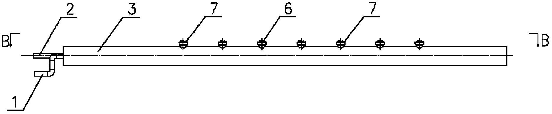
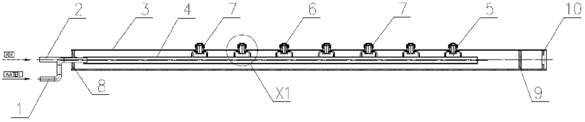
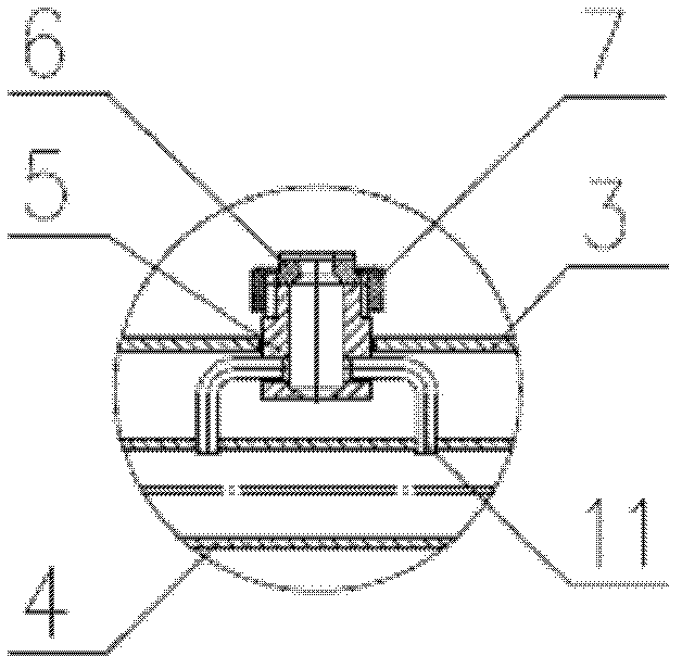
[0022] see Figure 1-7 , a combined nozzle for cooling plates, which includes a compressed air header 3, a cooling water header 4 is provided inside the compressed air header, and an inlet sealing plate 8 and an outlet sealing plate 9 are respectively provided at both ends of the compressed air header , the outer side of the sealing plate is provided with a transparent plate 10, the outer end of the inlet sealing plate is provided with a water supply pipe 1 and an air supply pipe 2, the water supply pipe communicates with the cooling water header, the air supply pipe communicates with the compressed air header, and the upper part of the compressed air header is set at intervals There are a plurality of nozzles, and the nozzles include an aerosol nozzle body 5 which is sealingly connected with a compressed air manifold. The aerosol nozzle body is connect...


PUM


Abstract

The invention relates to a combined spray pipe for a cooling plate, which comprises a compressed air manifold, wherein a cooling water manifold is arranged inside the compressed air manifold, and the two ends of the compressed air manifold are respectively provided with an inlet sealing plate and an outlet sealing plate; a water supply pipe and an air supply pipe are arranged at the outer end of the inlet sealing plate, and the water supply pipe is communicated with the cooling water manifold; the air supply pipe is communicated with the compressed air manifold, and a plurality of nozzles are arranged at the upper part of the compressed air manifold at intervals; each nozzle comprises an aerosol nozzle body, and the aerosol nozzle bodies are communicated with the compressed air manifold and are communicated with the cooling water manifold through water supply pipes of the nozzle bodies; and a spray head is arranged at the front end of each aerosol nozzle body. In the combined spray pipe, cooling water is atomized into fine particles to be sprayed to the surface of a cooling object under the action of compressed air, and the heat on the surface of the cooling object is brought by the strong heat exchange of fine liquid drops and the surface of the cooling object; and the cooling capacity of the aerosol spray pipe is adjusted by separately adjusting the flow rate of water.

Description

technical field [0001] The invention relates to a cooling device for heat treatment of plates and strips, in particular to a combined nozzle for cooling plates. Background technique [0002] At present, the technologies used for plate and strip cooling are mainly water spray cooling (WSC, Water Spray Cooling), gas jet cooling (AJC, Air Jet Cooling), etc., among which water spray cooling is widely used in plate and strip cooling. Rapid cooling, such as the rapid cooling section after the furnace of the CP unit, etc. Water spray cooling is that the cooling water is sprayed onto the surface of the cooling object through the cooling nozzle or the cooling nozzle at a certain pressure, a certain angle, and a certain water flow density. A cooling method for the object to be cooled. At present, there are mainly the following problems in water spray cooling: 1. Cooling capacity, water spray cooling capacity is related to factors such as the surface temperature of the object to be c...

Claims


Application Information

Patent Timeline
IPC IPC(8): C21D1/667C21D9/573
Inventor 张荣明袁立文刘国栋
Owner WISDRI WUHAN WIS IND FURNACE
Features
  • R&D
  • Intellectual Property
  • Life Sciences
  • Materials
  • Tech Scout
  • Unparalleled Data Quality
  • Higher Quality Content
  • 60% Fewer Hallucinations
Learn More