Mechanical drill rod

A technology of machine lock and drill pipe, which is applied in the direction of drill pipe, percussion drilling, rotary drilling, etc. It can solve problems such as drill sticking and incomplete unlocking, and achieves large loading force, convenient connection and disassembly, and excellent structure simple effect

Active Publication Date: 2013-08-14
WUCHANG SHIPBUILDING IND
View PDF6 Cites 0 Cited by
  • Summary
  • Abstract
  • Description
  • Claims
  • Application Information

AI Technical Summary

Problems solved by technology

[0002] The axial loading methods of existing pile driver drill pipes are divided into friction type and machine lock type, and the structure of existing machine lock type drill pipes is not completely unlocked, which is easy to cause drill sticking and other phenomena

Method used


Image

  • Mechanical drill rod

Examples


Embodiment Construction

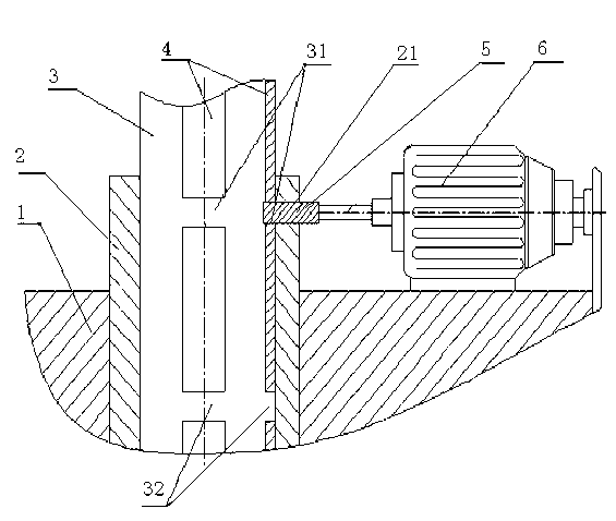
[0012] Such as figure 1 As shown, the embodiment of the present invention provides a machine-locked drill rod, which includes a drill rod body 3 , a loading device and a rotary power head 1 . Wherein, the loading device includes a loading block 5 and a set of linear power device 6 . The loading block 5 is connected with the linear power device 6, and the linear power device 6 is fixed on the rotary power head 1, and the rotary power head 1 is connected to the drill pipe body 3 through the output shaft 2; the drill pipe body 3 is provided with an external spline 4 in the axial direction , the outer spline 4 is provided with loading ports 31 and 32 in the axial direction (the number of loading ports is not limited to two); the output shaft 2 of the rotary power head 1 is provided with a loading hole 21 and the output shaft 2 is provided with an inner spline Key; loading block 5 is a cuboid shape. The loading ports 31 and 32 and the loading hole 21 match the size and shape of t...


PUM


Abstract

The invention discloses a mechanical drill rod. The mechanical drill rod comprises a drill rod body, a loading device and a rotary power head, wherein the loading device comprises a loading block and a set of linear power device; the loading block is connected with the linear power device; the linear power device is fixed on the rotary power head; and the rotary power head is connected to the drill rod body through an output shaft. The mechanical drill rod has a simple structure and is convenient to connect and disassemble and large in loading force.

Description

technical field [0001] The invention relates to the technical field of drill rods for drilling rigs, in particular to a machine-locked drill rod. Background technique [0002] The axial loading methods of existing pile driver drill rods are divided into friction type and machine lock type, and the structures of existing machine lock type drill rods all have incomplete unlocking, which easily causes phenomena such as drill sticking. Contents of the invention [0003] The object of the present invention is to provide a machine-locked drill pipe with simple and reasonable structure, convenient unlocking, and difficult rod jamming. [0004] In order to solve the above-mentioned technical problems, the present invention provides a machine-locked drill pipe, including a drill pipe body, a loading device and a rotary power head, the loading device includes a loading block and a set of linear power devices, and the loading block and the linear The power unit is connected, the li...

Claims


Application Information

Patent Timeline
Patent Type & Authority Patents(China)
IPC IPC(8): E21B17/00E21B3/02
Inventor 秦志应崔进社徐建华
Owner WUCHANG SHIPBUILDING IND
Why Eureka
Try Eureka