Gas drainage, dilution and mixing demister

A technology for gas extraction and mist eliminators, applied in mixers, gas discharge, mixers with rotary stirring devices, etc. Dryness, reduction in conveying power consumption, and cost reduction effects

Inactive Publication Date: 2013-06-19
SHANDONG UNIV OF TECH
View PDF2 Cites 0 Cited by
  • Summary
  • Abstract
  • Description
  • Claims
  • Application Information

AI Technical Summary

Problems solved by technology

[0004] In the patent "Oxidation Device Gas Mixing Intake System" (CN200920025062.2), the design of the main pipe and auxiliary pipe of the gas mixer is relatively complicated, and the high-concentration gas enters the gas from a very thin auxiliary pipe within 360° Intake main pipe increases the risk of explosion due to friction between high-concentration gas and wall surface
In the patent "Mixer for Coal Mine Drainage Gas and Ventilation Gas" (CN201010274136.3), the structure of the mixer is complex and the conical tailpipe of the gas injection pipe with evenly distributed small holes will bring great flow resistance , increasing the energy consumption of transporting gas
Moreover, none of the above patents has the function of dehumidification and diversion of gas extraction, and there is no gas dilution hybrid demister with relatively complete structure and performance.

Method used


Image

  • Gas drainage, dilution and mixing demister
  • Gas drainage, dilution and mixing demister
  • Gas drainage, dilution and mixing demister

Examples


Embodiment Construction

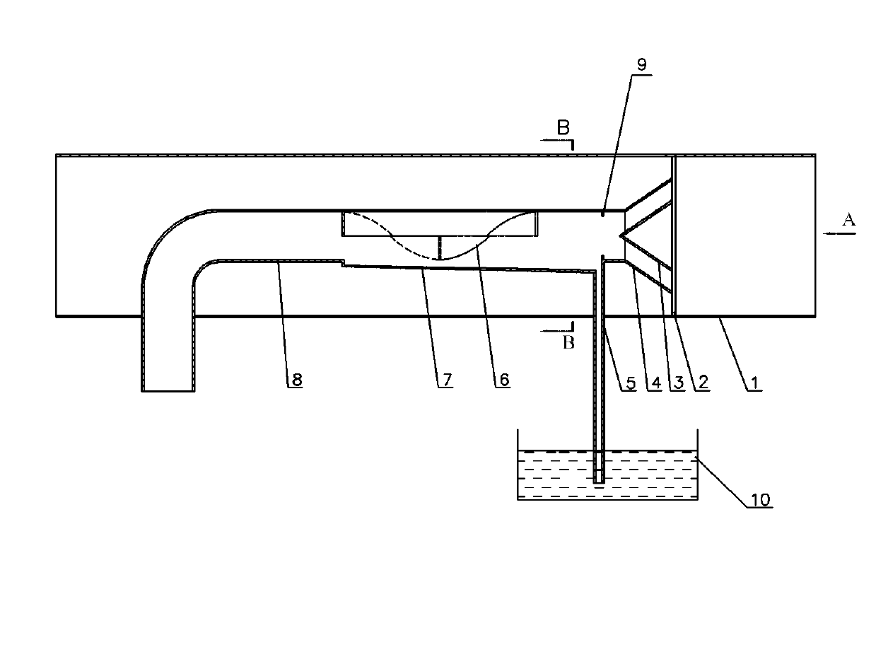
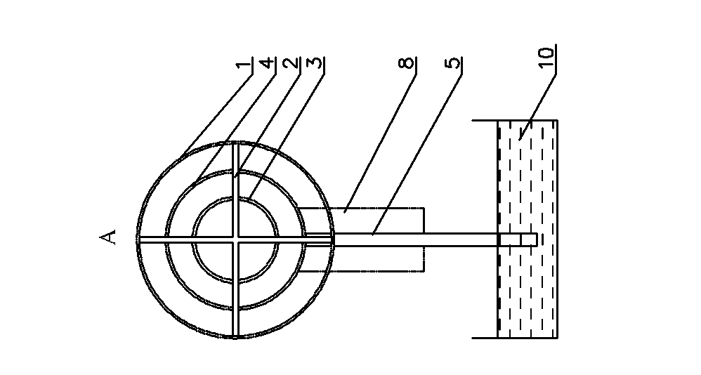
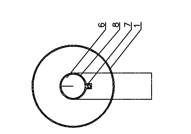
[0024] exist Figure 1-3 In the shown embodiment: it includes a tubular casing 1, a gas injection pipe, an inner helical blade 6, a baffle ring 9, a reinforcing rib 2, a diversion groove 7, a diversion pipe 5, a water seal groove 10 and a diversion Cone 3, the gas injection pipe includes an inlet pipe 8 and an expansion pipe 4 installed at the outlet end of the inlet pipe 8, wherein the inlet pipe 8 is a 90° elbow, the inlet end is set outside the shell 1, and the inlet pipe 8 is a straight pipe section close to the inlet end The straight pipe section vertically penetrating into the housing 1 and close to the outlet end is horizontally arranged in the housing 1, connected with the expansion tube 4 and facing the outlet end of the housing 1; the diversion cone 3 is a cone structure, located in the expansion tube 4, The pointed head faces away from the outlet end of the expansion tube 4, the expansion tube 4, the housing 1 and the diversion cone 3 are fixedly connected through t...


PUM


Abstract

The invention relates to a gas drainage, dilution and mixing demister, which comprises a shell, an inlet pipe and an expanding pipe, wherein the inlet pipe is a 90-degree bent pipe; an inlet end of the inlet pipe is arranged outside the shell; a straight tube section close to an inlet vertically penetrates into the shell; and a straight tube section close to an outlet is arranged in the shell, isconnected with the expanding pipe and faces the outlet end of the shell. The gas drainage, dilution and mixing demister is characterized in that: an inner helical blade, a flow baffling ring, reinforcing ribs, a flow guiding groove, a flow guiding pipe, a water seal groove and a flow guiding cone are additionally arranged; the flow guiding cone is positioned in the expanding pipe; the tip end of the flow guiding cone is back on to an outlet of the expanding pipe; the expanding pipe, the shell and the flow guiding cone are connected through the reinforcing ribs; the axial lines of the straighttube sections, the expanding pipe and the flow guiding cone are positioned at the axle center of the shell; the inner helical blade is fixed in the straight tube section at the outlet end of the inlet pipe; the flow guiding groove is formed on the lower pipe wall of the inlet pipe; the flow guiding pipe is arranged at the tail end of the flow guiding groove, runs through the shell and is insertedinto the water seal groove; and the flow baffling ring is fixed on the inner wall of the inlet pipe and is positioned on one side of the expanding pipe. The gas drainage, dilution and mixing demisterhas the advantages of humidity elimination, flow guidance, safe protection, low transmission energy consumption and the like.

Description

technical field [0001] The present invention relates to the gas supply equipment of the coal mine exhaust gas oxidation device, in particular to a coal mine exhaust gas oxidation device's extraction gas and exhaust gas or air dilution mixing demister, which belongs to ultra-low concentration methane thermal countercurrent oxidation and Low-density energy recovery technology field. Background technique [0002] Globally, coal mining releases about 49Mt of methane every year, accounting for about 9% of the total global methane emissions. The concentration of methane in the atmosphere is the fastest growing among all greenhouse gases. Due to its strong greenhouse effect, the emission of methane must be effectively controlled. my country extracts more than 5 billion cubic meters of gas every year. Among them, only 1 / 4 to 1 / 3 of the drainage gas is used, and the rest are in the state of emptying. In particular, low-concentration drainage gas with a concentration of less than 8...

Claims


Application Information

Patent Timeline
Patent Type & Authority Patents(China)
IPC IPC(8): E21F7/00B01F7/00B01D45/16
Inventor 高振强毛明明刘永启
Owner SHANDONG UNIV OF TECH
Why Eureka
Try Eureka