Automatic separation method for front and rear surface reflected light spots in surface shape detection system

A technology for detecting the front and rear surfaces and surface shapes, which is applied in the direction of measuring devices, optical devices, instruments, etc., can solve the problem of smearing on the rear surface of optical components, and achieve the effect of separation

Inactive Publication Date: 2012-01-18
SOUTHWEAT UNIV OF SCI & TECH
View PDF3 Cites 11 Cited by
  • Summary
  • Abstract
  • Description
  • Claims
  • Application Information

AI Technical Summary

Problems solved by technology

[0012] (3) When the front and rear light spots overlap, there is nothing to do
However, this method is difficult to implement after the optical components are installed and put on the shelf, because after the optical components are installed and put into operation, it is not allowed to apply Vaseline to the rear surface of the optical components

Method used


Image

  • Automatic separation method for front and rear surface reflected light spots in surface shape detection system
  • Automatic separation method for front and rear surface reflected light spots in surface shape detection system
  • Automatic separation method for front and rear surface reflected light spots in surface shape detection system

Examples


Embodiment 1

[0036] Separation method of front and rear reflection spots based on kalman filter

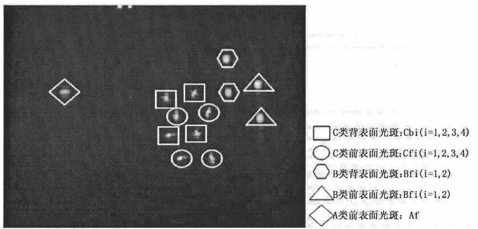
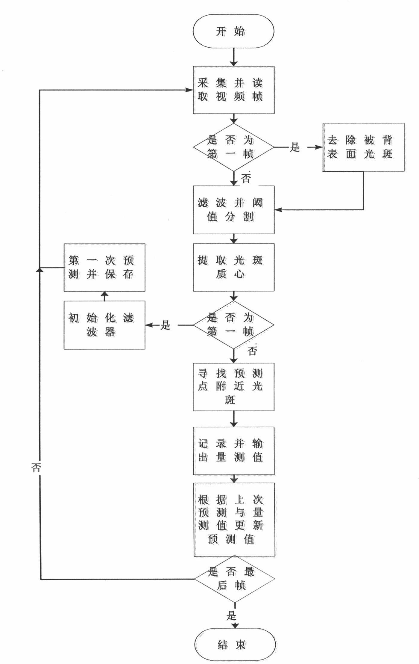
[0037] During the surface shape test, the reflected light spots on the back surface are artificially erased from the acquired first frame image, and all the reflected light spots on the front surface are tracked, so as to achieve the purpose of classifying the front and rear surface light spots. refer to figure 2 , its main steps are:

[0038] A1: The CCD collects the spot image F1 reflected by the front and rear surfaces; if it is the first frame image, manually erase the reflected spot on the back surface to select the correct target for subsequent tracking;

[0039] A2: Use the method of background subtraction and multiplicative filtering to filter out noise and perform iterative threshold segmentation to separate laser spots; obtain binary image F2;

[0040] A3: Detect all the light spots in the image F2, if there is adhesion of the light spots, separate the sticking light spots, and ex...

Embodiment 2

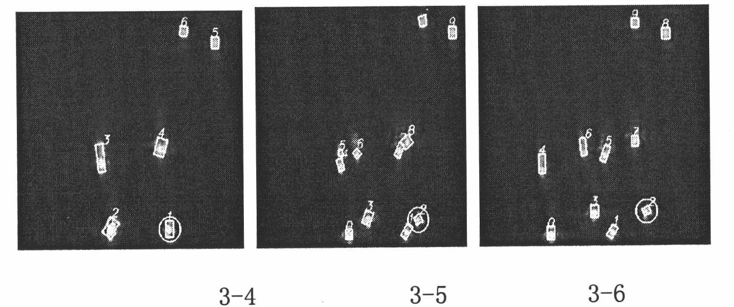
[0057] The tracking effect based on the Kalman filter is as follows: image 3 , image 3 The light spots in the middle rectangular frame are the detected light spots, and the light spots in the circular frame are the tracking front surface reflection spots. It can be found that in the case of the front and rear surface reflection spots, the tracking algorithm based on the Kalman filter can correctly distinguish For the light spots reflected on the front surface, the statistics of multiple experimental results show that the tracking accuracy rate is above 95%.

Embodiment 3

[0059] Experimental results of overlapping spot separation based on distance transformation

[0060] In the experiment, three types of laser spots were overlapped and separated: (1) The spots with basically the same size and not serious overlapping ( Pic 4-1 ); (2) overlapping spots of inconsistent size ( Figure 4-2 ); (3) Spots with basically the same size and serious overlapping ( Figure 4-3 ). in, Pic 4-1 , Figure 4-2 and Figure 4-3 From left to right in the middle are the original image, the segmentation effect image, the circle center area image, and the separation result image. Experimental results show that the method of the present invention can well realize the separation of overlapping light spots.


PUM


Abstract

The invention discloses an automatic separation method for front and rear surface reflected light spots in a surface shape detection system. The method comprises the following steps of: A1, acquiring a current front and rear surface reflected light spot image F1 by a charge coupled device (CCD); A2, filtering noise by adopting a method combining background subtraction and multiplication filtration, and performing iterative threshold segmentation to obtain a binary image F2; A3, detecting all light spots in the image F2, and extracting the centroid of all the light spots; A4, tracking with a Kalman filter; A5, searching a nearest light spot centroid around the last predicted centroid, outputting the nearest light spot centroid, transmitting all found front surface reflected light spot centroid data to the Kalman filter, and predicting the position of the light spot centroid of the next frame by using the last predicted data and the actual extracted data through the Kalman filter; and A6, if the position is the data of the last frame, ending. The Kalman filter-based tracking algorithm accurately distinguishes the front surface reflected light spots, and the experimental result statistics of multiple times shows that the tracking accuracy is more than 95 percent.

Description

technical field [0001] The invention relates to a method for automatically separating reflected light spots on front and rear surfaces in a surface shape detection system, and belongs to the field of surface shape detection technology and image processing of optical components. Background technique [0002] In the surface shape detection process based on the angle difference method, the detection laser is reflected by the front and rear surfaces of the optical component, and then passes through the optical system to form front and rear surface spots on the CCD. When the parallelism between the front and rear surfaces of the optical element is very high, the angle between the measured reflected light on the front and rear surfaces corresponding to the same measurement point is very small, resulting in overlapping spots on the CCD. If the center of mass is calculated by considering the overlapping spots as a whole, a large calculation error will be introduced, resulting in an ...

Claims


Application Information

Patent Timeline
Patent Type & Authority Applications(China)
IPC IPC(8): G01B11/24
Inventor 范勇王俊波袁晓东徐旭熊召陈念年巫玲
Owner SOUTHWEAT UNIV OF SCI & TECH
Why Eureka
Try Eureka