Digital liquid level sensor

A liquid level sensor and sensor technology, applied in liquid level indicators for physical variable measurement, etc., can solve problems such as inability to match subsequent digital processing circuits, and achieve the effects of easy replacement, low cost, and simple production

Inactive Publication Date: 2012-01-18
TAIYUAN UNIV OF TECH
View PDF4 Cites 6 Cited by
  • Summary
  • Abstract
  • Description
  • Claims
  • Application Information

AI Technical Summary

Problems solved by technology

[0005] The purpose of the present invention is a digital liquid level sensor, which aims to solve the disadvantages of the existing liquid level sensor that the output signal is an analog signal and cannot be completely matched with the subsequent digital processing circuit, ther

Method used


Image

  • Digital liquid level sensor
  • Digital liquid level sensor
  • Digital liquid level sensor

Examples


Embodiment approach 1

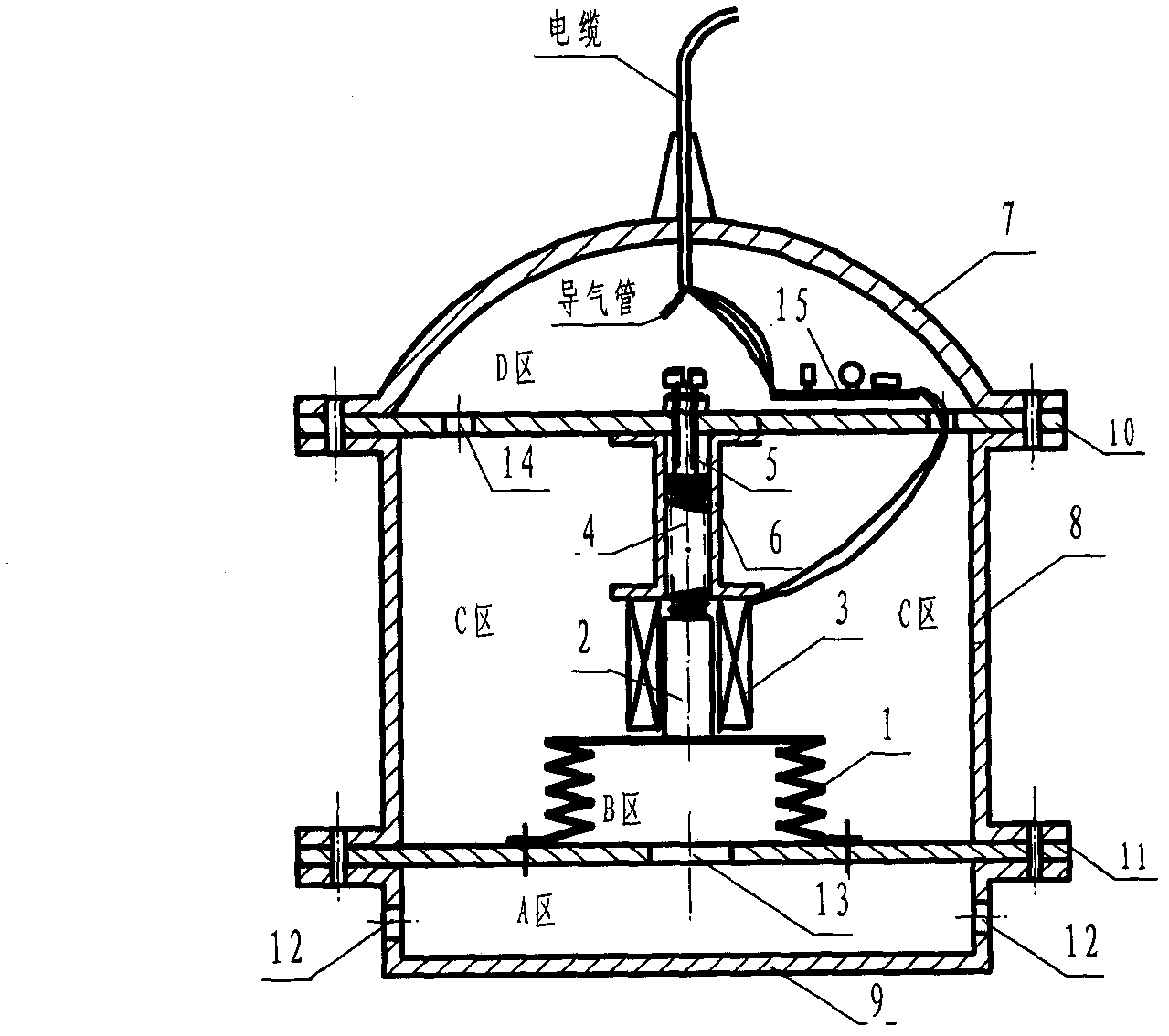
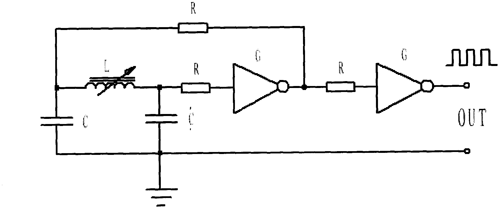
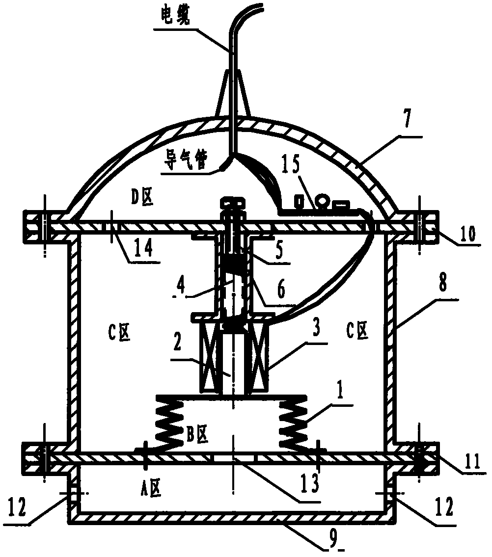
[0021] Such as figure 1 , a digital liquid level sensor of the present invention is composed of a sensing part, a housing and a transmitter 15, and the sensing part is composed of a rubber mold box 1, a magnetic core 2, a coil 3, a spring 4 and an adjusting screw 5, wherein The rubber mold box 1 is a rubber elastic cavity that stretches up and down. The magnetic core 2 is fixed on the upper end of the rubber mold box 1 to make it integrated. The lower end of the mold box 1 is fixed on the center of the lower support plate 11. 6 is fixed on the center of the upper support plate 10, the magnetic core 2 penetrates the coil 3, the spring 4 withstands the upper end surface of the magnetic core 2, adjusts the adjustment screw 5 to adjust the pressure of the spring 4 on the magnetic core 2, when there is a force When placed at the upper end of the inner cavity of the rubber mold box 1, the magnetic core 2 will move up and down in the coil 3; The cable of the trachea is drawn from th...

Embodiment approach 2

[0030] A digital liquid level sensor of the present invention is applied on a certain water storage tank. According to the actual height of the water storage tank of 10m, the adjusting screw 5 is adjusted so that the maximum range of the digital liquid level sensor is 9.5m. According to the output frequency f m =36kH and f 0 = 3.16kH to calculate the pulse equivalent, pulse equivalent = 9500 / (36000-3160) = 0.29mm / pulse, the same output frequency decreases by one pulse, the water level increases by 0.29mm; on the contrary, each time the output frequency increases by one pulse, the water level decreases by 0.29mm, Store the pulse equivalent of 0.29mm / pulse into the intelligent digital display as the basis for calculating the water level. Others are the same as Embodiment 1.

Embodiment approach 3

[0032] The application of a digital liquid level sensor of the present invention on an oil storage tank, the difference between measuring the oil level and measuring the water level is that the sensor must be resistant to oil when measuring the oil level, and at the same time must have explosion-proof measures. The rubber mold box 1 is replaced with an oil-resistant Rubber mold box, transmitter 15 power supply adopts intrinsically safe power supply. Others are the same as Embodiment 2.


PUM


Abstract

The invention relates to a digital liquid level sensor, belonging to the technical field of measurement. The digital liquid level sensor is characterized in that the sensor is an integral throw-in-type digital liquid level sensor with an elastic cavity, the sensor consists of a sensing part, a shell and a transmitter 15, and the sensing part (see attached drawing 1) consists of a rubber molded box 1, a magnetic core 2, a coil 3, a spring 4 and an adjusting screw 5, wherein the rubber molded box 1 is a rubber elastic cavity which can be extended and retracted vertically, and the transmitter 15 and the sensing part are installed together. When being used, the digital liquid level sensor is directly thrown into liquid to be detected and is not required to be installed. Moreover, since the sensor outputs pulse digital signals, the sensor can be directly matched with subsequent digital processing circuits such as a computer, a single-chip microcomputer and the like. The digital liquid level sensor has the advantages of low manufacturing cost, simple range adjustment and convenience in use, is suitable for all fields of industry and agriculture and can be used for measuring the liquid level of all kinds of conductive and nonconductive liquid materials.

Description

technical field [0001] The invention relates to a digital liquid level sensor, which belongs to the technical field of measurement, and is an input-type digital liquid level sensor with an integrated structure of an elastic cavity to output a pulse signal, which can directly match with a subsequent digital processing circuit. It is suitable for measuring the liquid level of various conductive or non-conductive liquid materials, and has the advantages of simple structure, convenient installation, low cost, large measuring range and wide application range. Background technique [0002] Sensors are sensing components for measuring various process parameters. There are various types of sensors, such as temperature, pressure, flow, liquid level, speed, voltage, current and other sensors. Common liquid level sensors have various forms such as differential pressure type, resistive type, capacitive type, ultrasonic type, radar type, and input type. Most of these sensors output analo...

Claims


Application Information

Patent Timeline
IPC IPC(8): G01F23/26
Inventor 张英梅白雪峰王丽王丽娟
Owner TAIYUAN UNIV OF TECH
Why Eureka
Try Eureka