Method for measuring high energy laser energy parameter based on light pressure principle and apparatus thereof

A high-energy laser and principle technology, applied in the field of high-energy laser parameter measurement, can solve problems such as difficult continuous wave high-energy laser parameter measurement, achieve wide applicability, and improve the effect of cost-effectiveness

Active Publication Date: 2012-01-18
NORTHWEST INST OF NUCLEAR TECH
3 Cites 28 Cited by

AI-Extracted Technical Summary

Problems solved by technology

The device does not interrupt the beam in application, and can realize online monitoring of laser energy parameters, but the problem is that due to the twisted stru...

Abstract

The invention discloses a method for measuring a high energy laser energy parameter based on a light pressure principle and an apparatus thereof. The method comprises the following steps: a reflector and a deformation rod are arranged on a high energy laser incidence optical path, a plurality of displacement sensors are provided at a back side of a reflector laser incidence direction, micrometricdisplacement of the reflector caused by light pressure in a laser light extraction process is measured in real time, a light pressure value generated by laser is solved, and parameters of the laser such as average power, energy, P-t curve, light spot center of mass change and the like are calculated. According to the method and the apparatus in the invention, light beam is not blocked in usage, an on-line measurement of undistributed transmission of high energy laser is realized, cost-effectiveness of an experiment is raised, simultaneously, a measurement system does not need to bear strong laser irradiation, and the method and the apparatus can be used for high power laser parameter measurement.

Application Domain

Technology Topic

Image

  • Method for measuring high energy laser energy parameter based on light pressure principle and apparatus thereof
  • Method for measuring high energy laser energy parameter based on light pressure principle and apparatus thereof
  • Method for measuring high energy laser energy parameter based on light pressure principle and apparatus thereof

Examples

  • Experimental program(1)

Example Embodiment

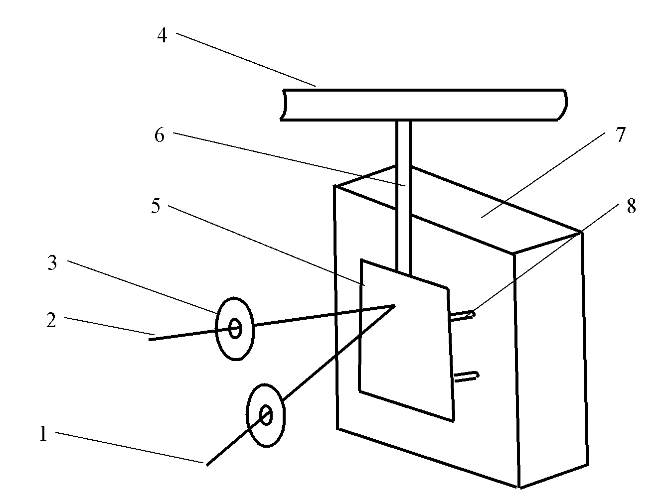
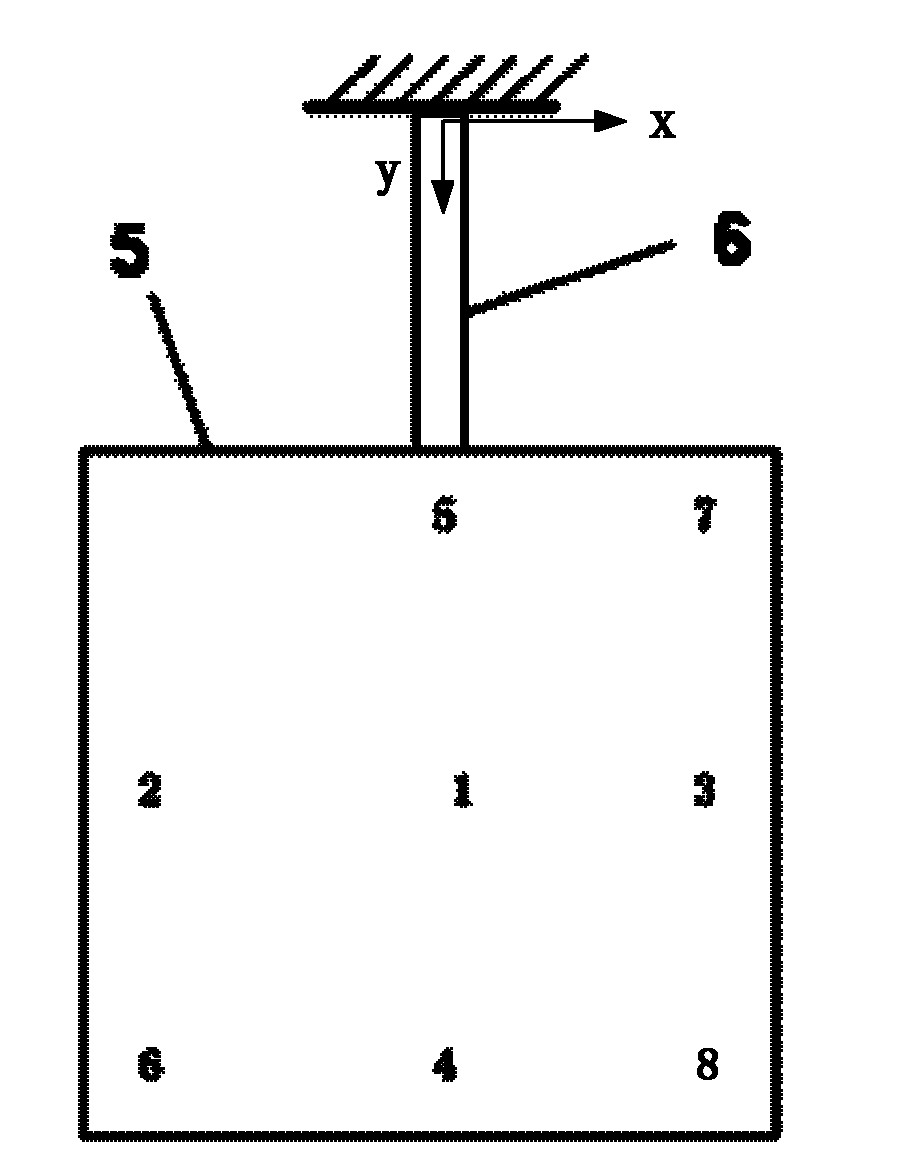
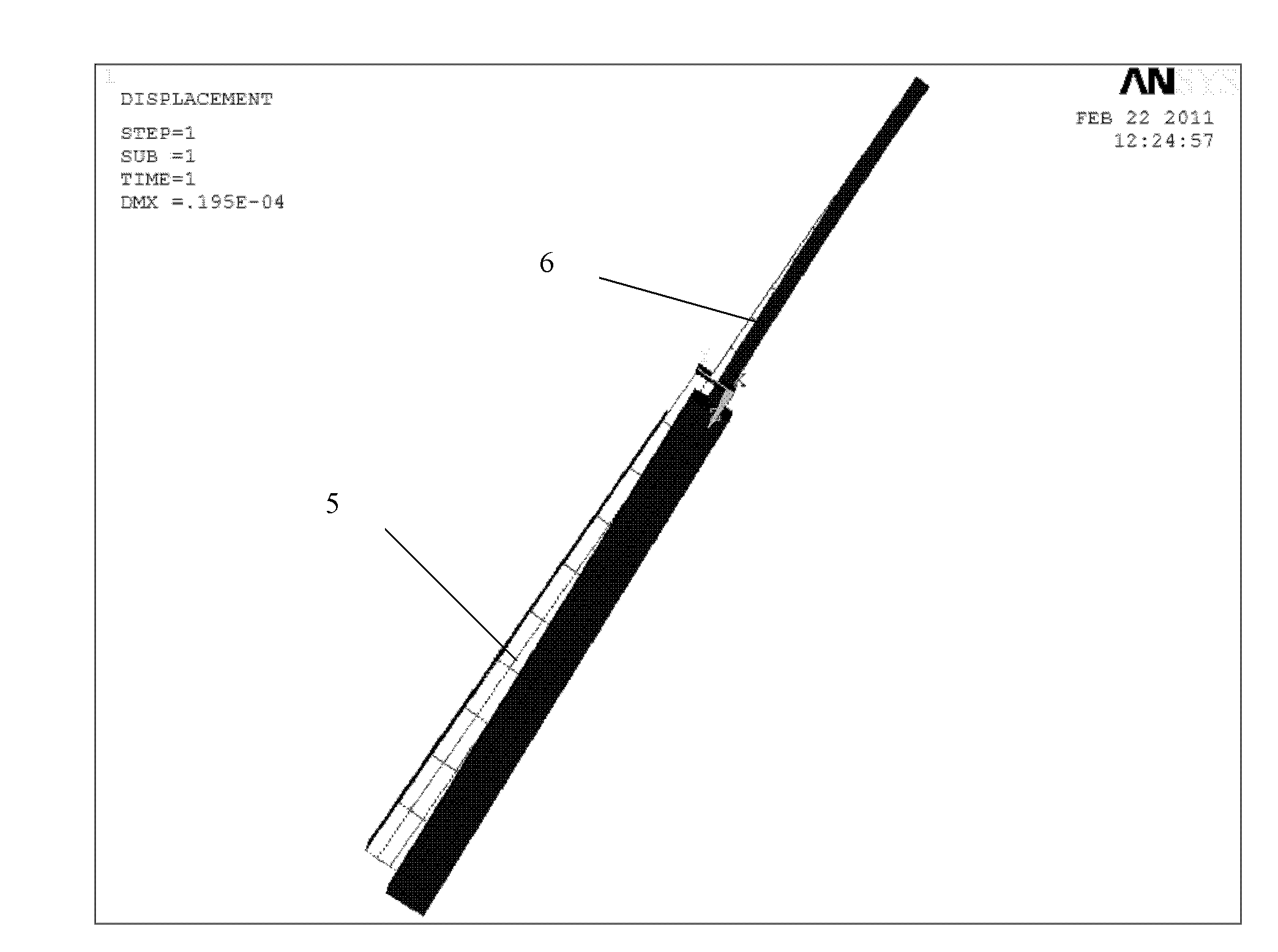
[0048] The present invention proposes a high-energy laser energy parameter measurement method based on measuring dynamic light pressure. The high-energy laser is incident on a mirror 5 with a deformable rod 6, and the multi-point dynamics of the mirror 5 under the laser light pressure are accurately measured. Displacement, calculated parameters such as laser energy.
[0049] According to the classical electromagnetic field equation, it can be calculated that when light is incident on a total reflection surface, the light pressure F and the light power I borne by the reflection surface can be expressed as
[0050] F=2·I·cosθ/c (1)
[0051] Among them: c is the speed of light; θ is the angle between the light incident direction and the normal of the reflecting surface. For a 200kW high-energy laser, the pressure caused by the vertical incidence to the specular reflection is about 136mg force. Estimated at 100 times the dynamic range of the measurement system, the minimum resolution of the measurement system pressure needs to reach 1.36mg or more.
[0052] The measurement of mg-level force is a technical problem. However, with the development of weighing instrument technology in recent years, precision balances based on the principle of electromagnetic induction and capacitance parameter change measurement have appeared. The basic principle of this principle is to use deformable parts to convert mg-level force into Micro displacement, the weight of the object can be obtained through accurate measurement of displacement. The resolution of the existing precision balance can reach the μg level, but it is difficult to directly apply to the measurement of high-energy laser light pressure. The main reason is that the method of measuring micro-mass by the precision balance is static measurement, and it must meet the existing high-energy laser parameter measurement method. For dynamic measurement, the measurement system needs to meet certain dynamic response characteristics. This is because the output power and spot shape of the existing high-energy lasers are not stable. The power change with time (Pt) curve is similar to the high-level superimposed part of the slowly varying small amplitude level, the spot shape There is also a slow changing process with time. Therefore, in order to accurately describe the characteristics of high-energy lasers, it is necessary to measure the average power of the laser, the Pt curve, the energy value, the centroid of the incident spot, and the change of the centroid with time.
[0053] Such as figure 1 As shown, the idea of ​​the present invention is to set a reflector 5 on the optical path of the high-energy laser, the reflector 5 is substantially perpendicular to the direction of the incident beam 2, and the reflector 5 is fixed above the casing 4 of the instrument by a deforming rod 6 . In order to collect all the laser light, the scale of the mirror 5 is greater than or equal to the beam scale. The surface of the mirror 5 is coated with a high-reflection film for the laser wavelength after finishing. The high-reflection film can be a multilayer dielectric reflection film. The coating process has a reflectivity of over 99.9%, which can meet high-energy laser measurement without being damaged.
[0054] The deforming rod 6 and the reflecting mirror 5 are made of silicon, quartz or silicon carbide and other dielectric materials. The deforming rod 6 and the reflecting mirror 5 are integrated processing, or they can be separately processed and fixed. The size and structure design of the deforming rod 6 is the key of the present invention, which not only needs to satisfy the dynamic response of the laser light pressure measurement, but also generates sufficient deformation under the action of light pressure. On the back of the reflector 5 and the laser incident direction, as close as possible to the edge position, there are multiple displacement sensor probes 8 installed. The preferred method is 2 or 4 non-contact displacement sensor probes 8. The displacement sensor can be selected based on Optical fiber principle non-contact micro-displacement sensor or capacitance principle non-contact displacement sensor, its measurement resolution can reach 1nm, and the measurement range can reach several μm. When using displacement sensors with different working principles, the backlight surface of the reflector 5 may be subjected to a process such as diffuse reflection or reflection film coating as required to meet the measurement of micro-displacement parameters.
[0055] The displacement sensor measures the displacement of the light pressure at different points of the reflector 5 during the laser emission in real time, and combines the numerical simulation of the reflector 5 and the overall calibration results to calculate the light pressure value generated by the laser, and then according to the relationship between light pressure and energy , Get the laser's average power, energy, Pt curve and spot centroid change and other parameters.
[0056] In order to reduce the influence of external temperature, vibration, air disturbance, etc. on the measurement system, the measurement system is installed in a sealed casing 4 ( figure 1 Only part of the housing structure is given), the measured laser light enters the reflector through the incident window and then exits through the exit window. The window material can be a material with high transmittance to the wavelength of the laser. At the same time, a constant temperature device is built in the housing of the entire measurement system, and a shock-absorbing component is designed at the bottom of the casing 4. The shock-absorbing component can be a spring, a sponge or other combined components.
[0057] In order to increase the light pressure value, it is desirable that the angle between the normal line of the mirror surface of the laser incident direction is as small as possible, but considering that the laser returning along the original path may damage the optical device, the angle between the direction of laser incidence and the normal line of the reflector is set to 45 °~85°.
[0058] In order to verify the feasibility of the present invention, in conjunction with the accompanying drawings and specific embodiments, the key of the present invention-the characteristics of the reflector 5 and the deforming rod 6 under the action of micro pressure, are simulated and calculated. in figure 2 In the example in the example, the reflector 5 and the deformable rod 6 are designed as a simple cantilever beam structure. The parameters of the reflector 5 are 40mm×40mm and the thickness is 3mm; the cross section of the deformable rod 6 is 4mm×1mm rectangular structure and the height is 25mm. , Both materials are made of quartz, and the deformable rod 6 is fixed at the central part of the upper part of the reflector 5 and is integrated with the reflector 5 for processing. On the mirror 5, 1#, 2#, 3#, 4#, and 5# are used as the force application points, and 6# and 7# are the displacement measurement points. The force direction and the displacement direction are both perpendicular to the mirror 5. Working surface.
[0059] The specific solution method from displacement to pressure and force position coordinates is given below:
[0060] in figure 2 In the rectangular coordinate system shown, the center of the upper end of the deforming rod 6 is the origin of the coordinates, the length direction of the deforming rod 6 is the y-axis, and the width direction is the x-axis. Let the pressure be F, and the force point coordinates are (x, y ), the coordinate of the displacement measuring point is (x 0 , Y 0 ).
[0061] The displacement δ caused by the pressure F at the displacement measurement point includes the displacement δ′ caused by the bending of the deformed rod on the y-axis caused by the pressure F and the displacement δ′ caused by the distortion of the deformed rod 6 around the y-axis caused by the pressure F.
[0062] According to the related principles of material mechanics cantilever beam, there are:
[0063] δ ′ = F · y 0 2 ( y 0 - 3 y ) / 6 EI - - - ( 2 )
[0064] δ″=F·x·x 0 /GI t (3)
[0065] Then in (x 0 , Y 0 ) Displacement obtained by the displacement sensor arranged in point coordinates
[0066] δ = δ ′ + δ ′ ′ = F · y 0 2 ( y 0 - 3 y ) / 6 EI + F · x · x 0 / GI t - - - ( 4 )
[0067] Among them: EI means bending stiffness, GI t It indicates the torsional stiffness, which depends on the material and structure of the mirror 5 and the deforming rod 6.
[0068] Formula (4) contains three unknown quantities F, x, and y, so it is necessary to place displacement sensors at at least three different positions of the reflector, and calculate the above three variables, and then combine formula (1) to calculate The power of the incident laser and the position of the center of mass of the spot, and the final integration of the laser power within the light emitting time can also obtain the total energy of the incident laser.
[0069] Table 1 shows the displacement changes of the mirror 5 at the measuring points of 6# and 7# in the direction perpendicular to the paper surface at the points 1#, 2#, 3#, 4#, and 5# calculated by using ANSYS software. value, image 3 When the static force of 1mg is loaded at point 1#, the displacement simulation diagram of the mirror 5, the shaded part in the figure is the position of the deformed rod 6 and the mirror 5 after the force is applied, and the non-shaded part is the deformed rod 6 and before the force The location of the mirror 5.
[0070] Table 1: Displacement change values ​​of two measuring points when 1mg static force is loaded at different application points
[0071]
[0072] The simulation results show that when the same 1mg force is applied at different positions, the displacements of the two measuring points are different. The displacement of the 6# measuring point far away from the deformation rod 6 changes greatly; when the force application point deviates from the mirror 5 and the deformation rod 6 When it is on the axis (such as 2# and 3# points), it will cause local torsion of the deformed rod, resulting in inconsistent changes in displacement as shown in Table 1. This also shows that by measuring the displacement changes at different points of the reflector 5, the position of the light pressure application point, that is, the center of mass of the spot can be inversely deduced, and the change of the displacement with time can be used to obtain the change of the spot center of mass with time. For high-energy lasers The performance analysis of the system is of great significance.
[0073] In order to further verify the dynamic response characteristics of the mirror 5 under alternating loads similar to the time characteristics of high-energy lasers, figure 2 The 1# position of the mirror 5 shown is simulated to be loaded with an alternating force, the average amplitude of the force is 10 mg, and a sinusoidal alternating force with an amplitude of 1 mg is superimposed on the average amplitude. The frequency is 20 Hz. Based on years of experience in high-energy laser parameter measurement and analysis of high-energy laser spectrum characteristics, the high-energy laser output Pt curve is similar to the average power superimposed on the basis of part of the slowly varying small amplitude power change, the change frequency is usually within 20Hz, For other very small amounts of high-frequency variation components can be ignored in the measurement, so the above loading model can reflect the time characteristics of high-energy laser. Figure 4 (a) is the time-varying characteristics of the simulated alternating loading force, Figure 4 (b) is the corresponding dynamic displacement result of the mirror 5 obtained by numerical simulation. From the comparison of the amplitude and frequency parameters of the dynamic response, within the response frequency band of 20 Hz, the dynamic characteristics of the mirror 5 can satisfy the measurement of the existing high-energy laser parameters. If the dynamic response compensation technology is adopted, the frequency band range of the reflector 5 and the deforming rod 6 can be further increased, and the measurement requirements can be better met.
[0074] The present invention is not limited to the above-mentioned specific embodiments. For example, the number of deformable rods 6 can be more than one, and the fixing position with the reflector 5 is not limited to the central part of the upper part of the reflector 5. For example, it can be fixed on the back of the reflector 5. In addition to being fixed on the upper part of the casing 4, the deformable rod 5 can also be fixed on the side of the casing 4; the number of displacement sensing probes 8 is not limited to 2 or 4, and it is also installed on the backlight surface of the reflector 5. Not limited to the edges. The above changes are all within the protection scope of the present invention.

PUM

no PUM

Description & Claims & Application Information

We can also present the details of the Description, Claims and Application information to help users get a comprehensive understanding of the technical details of the patent, such as background art, summary of invention, brief description of drawings, description of embodiments, and other original content. On the other hand, users can also determine the specific scope of protection of the technology through the list of claims; as well as understand the changes in the life cycle of the technology with the presentation of the patent timeline. Login to view more.

Similar technology patents

Multi-stage perforating pressurizing device

Owner:CHINA PETROLEUM LOGGING CO LTD +1

Classification and recommendation of technical efficacy words

  • Wide applicability
  • High cost-effective

Ignition interlock device and method

Owner:INTERCEPTOR IGNITION INTERLOCKS

Beam feeding method suitable for small-curve-radius girder erection

ActiveCN109440645ALow construction costHigh cost-effectiveBridge erection/assemblyGirder bridgeStructural engineering
Owner:CHINA RAILWAY NO 2 ENG GRP CO LTD +1
Why Eureka
Try Eureka