
Lubrication simulation device for piston ring and cylinder sleeve of engine

A technology of simulating device and piston ring, which is applied in the testing of engine, measuring device, testing of mechanical parts, etc., can solve the problem of splash lubrication of piston ring-cylinder liner, difficulty in evaluating friction and wear characteristics of friction pair, lubrication The problem of uneven oil distribution can achieve the effect of significant simulation effect, low cost and solving the problem of partial wear.

Inactive Publication Date: 2012-01-18
CHINA NORTH IND GRP NO 70 RES INST
View PDF5 Cites 3 Cited by
  • Summary
  • Abstract
  • Description
  • Claims
  • Application Information

AI Technical Summary

Problems solved by technology

The system can simulate the reciprocating sliding motion of the piston ring-cylinder liner, can realize the radial expansion and tightening of the piston ring to the cylinder liner, and can also realize the ambient temperature of the friction pair through resistance heating. However, the piston ring-cylinder liner has not been solved well. The splash lubrication between the sets leads to uneven distribution of lubricating oil during the test, and serious eccentric wear occurs, which brings great difficulties to the evaluation of the friction and wear characteristics of the friction pair in the later stage

Method used


Image

  • Lubrication simulation device for piston ring and cylinder sleeve of engine
  • Lubrication simulation device for piston ring and cylinder sleeve of engine
  • Lubrication simulation device for piston ring and cylinder sleeve of engine

Examples


Embodiment Construction

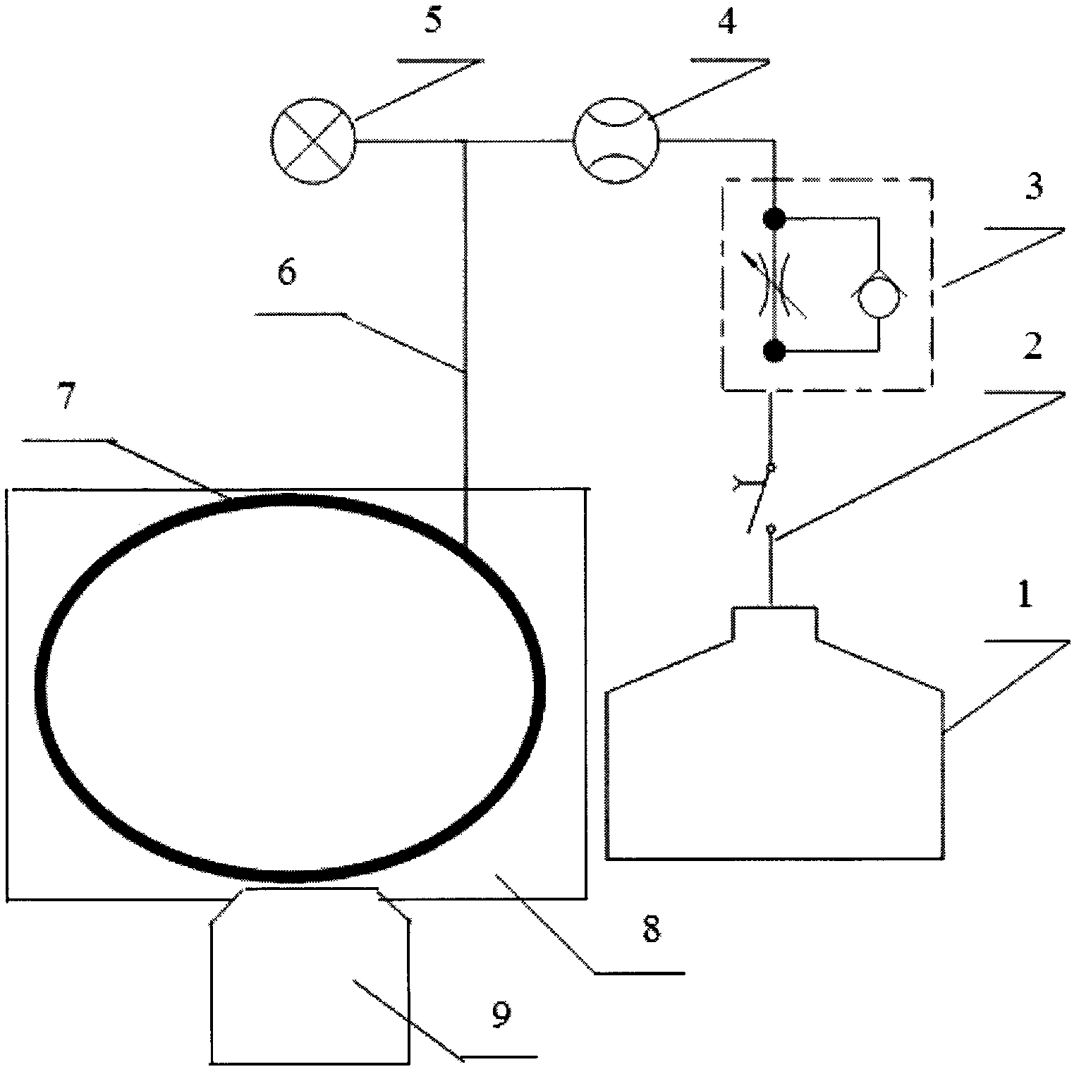
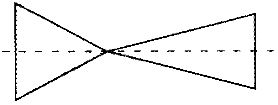
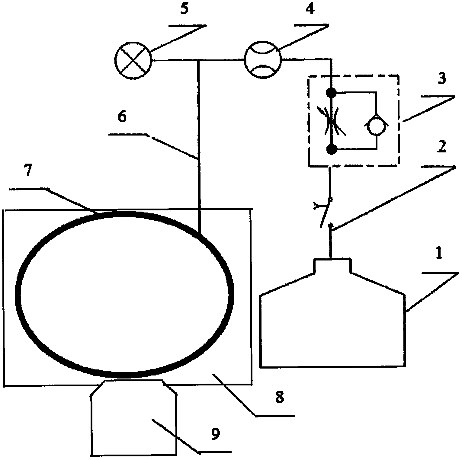
[0010] An engine piston ring and cylinder liner lubrication simulation device, which includes a lubricating oil tank 1, a timing controller 2, an electronic pump 3, a flow pump 4, a pressure gauge 5, a plastic hose 6, an oil injection copper pipe 7, an annular clamp 8 and an upper The piston 9 and the lubricating oil tank 1 are connected to the oil injection copper pipe 7 through the plastic hose 6, the plastic hose 6 is connected to the timing controller 2, the electronic pump 3, the flow pump 4, and the pressure gauge 5, and the oil injection copper pipe 7 is evenly arranged There are more than two double-horn-shaped nozzles, it is believed that the distance between the two double-horn-shaped nozzles is 10mm, and the angle between the axis and the normal of the double-horn nozzles is 30°, and the described fuel injection copper pipe 7 is arranged on In the ring groove of the ring clamp 8, the ring clamp 8 is connected with the upper piston 9, and the cross-sectional shape of ...


PUM


Abstract

The invention relates to a lubrication simulation device for a piston ring and a cylinder sleeve of an engine. A lubricating oil tank (1) is connected with an oil spray copper pipe (7) through a plastic hose (6); the plastic hose (6) is connected with a timing controller (2), an electronic pump (3), a flow pump (4) and a pressure gauge (5); more than two double-trumpet-shaped spray holes are uniformly formed on the oil spray copper pipe (7); the hole distance between two adjacent double-trumpet-shaped spray holes is 10 millimeters; the included angle between the axis and the normal line of each double-trumpet-shaped spray hole is 30 degrees; the oil spray copper pipe (7) is arranged in an annular groove of an annular fixture (8); the annular fixture (8) is connected with an upper piston (9); and the cross section of a connecting surface between the annular fixture (8) and the upper piston (9) is conical. The device is used for simulating the splash lubrication state of a piston ring-cylinder sleeve friction pair in the engine, runs stably and reliably, and has a good lubrication simulation effect. By adopting the lubrication simulation device, the problem of camber wear of a cylinder sleeve-piston ring is solved.

Description

technical field [0001] The invention belongs to the field of engines, in particular to an engine piston ring and cylinder liner lubrication simulation device. Background technique [0002] In the current situation of severe energy and environmental protection issues, the requirements for internal combustion engines are becoming more and more stringent, coupled with high speed and high load, extended service life and long-term continuous operation, etc., it is urgent to improve the wear resistance of friction pairs in internal combustion engines, reduce the wear resistance caused by Power lost through friction. [0003] Studies have shown that the friction power consumption caused by the reciprocating friction pair piston ring-cylinder liner in the internal combustion engine can account for 65% of the friction power consumption of the entire engine when it is at its maximum, and its friction, wear and lubrication performance directly affect the power consumption of the engine...

Claims


Application Information

Patent Timeline
Patent Type & Authority Applications(China)
IPC IPC(8): G01M15/00G01M13/00G01N3/56
Inventor 王建平刘长振宋吉林杨建绩强慧
Owner CHINA NORTH IND GRP NO 70 RES INST
Learn More