Method for bonding upper and lower magnetic cores of module power supply

A module power supply and magnetic core technology, applied in the direction of assembling printed circuits with electrical components, can solve the problems of discontinuous process, many operator demands, and damage to the edge of the magnetic core, and achieve the effect of reducing the defect rate of inductance

Active Publication Date: 2012-01-18
SHENZHEN VAPEL POWER SUPPLY TECH
View PDF3 Cites 5 Cited by
  • Summary
  • Abstract
  • Description
  • Claims
  • Application Information

AI Technical Summary

Problems solved by technology

[0003] 1. Because clamping the magnetic core with a clip will put a pressure on the surface of the magnetic core, it often causes damage to the edge of the magnetic core. At the same time, the magnetic core is placed in the tray without fixing, and it collides with each other during transportation, resulting in edge defects; resulting in poor appearance and a large amount of repairs. , the defect rate is more than 5%;
[0004] 2. It takes a long time to put the tray into the oven for baking. The number of ovens is limited, and the daily output cannot be increased. If you want to increase the production capacity, you need to add a lot of ovens
[0005] 3. The process is discontinuous and the operation is not smooth, resulting in low production efficiency, which is not conducive to operation, and the demand for operators is high

Method used


Image

  • Method for bonding upper and lower magnetic cores of module power supply
  • Method for bonding upper and lower magnetic cores of module power supply
  • Method for bonding upper and lower magnetic cores of module power supply

Examples


Embodiment Construction

[0015] The present invention will be described in detail below with reference to the accompanying drawings and in combination with preferred specific embodiments.

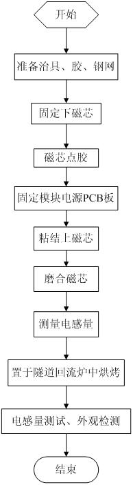
[0016] like figure 1 As shown, the magnetic core bonding method of the module power supply of this embodiment includes the following steps:

[0017] 1) Preparation stage

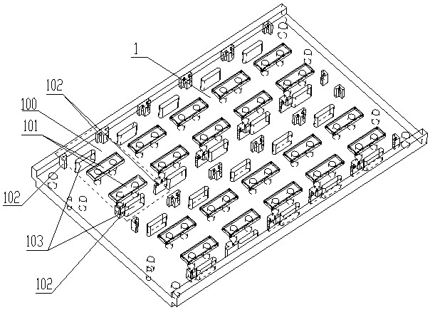
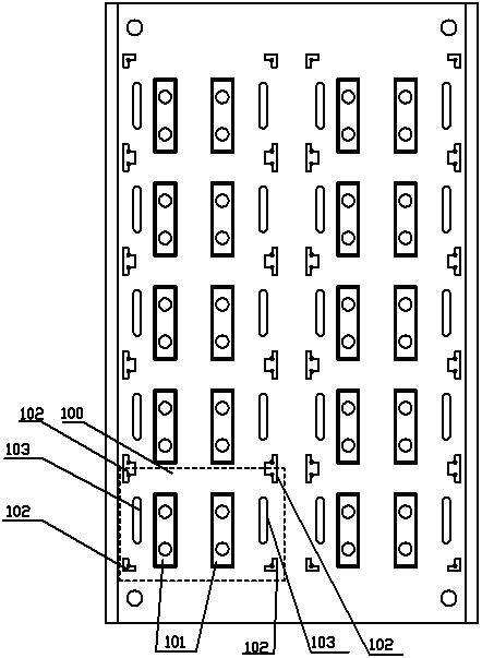
[0018] Prepare glue and fixtures. The structure of the fixture is as figure 2 , 3 As shown, the jig of this embodiment is a piece of aluminum plate 1. Ten module power supply fixing units 100 are arranged on the aluminum plate 1. The fixing unit 100 includes two magnetic core fixing slots 101 corresponding to the size of the lower magnetic core. The module power supply The two lower magnetic cores can be respectively fixed in the two magnetic core fixing grooves 101; the four corners of the fixing unit 100 are respectively provided with a module power supply PCB board fixing column 102, and the fixing unit 100 is also provided with two modul...


PUM


Abstract

The invention discloses a method for bonding upper and lower magnetic cores of a module power supply. The upper and lower magnetic cores of the module power supply are bonded on a PCB (printed circuit board) of the module power supply, and the method comprises the step of bonding and the step of baking and curing. The step of bonding comprises the following steps: A1) the lower magnetic cores are fixed on a prepared jig, and adhesive dispensation is carried out on the bonding positions of the lower magnetic cores and the PCB of the module power supply, and on the bonding positions of the lower magnetic cores and the upper magnetic cores; A2) the PCB of the module power supply and the lower magnetic cores are aligned and covered, so the bonding positions of the upper and lower magnetic cores pass through corresponding installation holes on the PCB of the module power supply, and the position of the PCB of the module power supply is fixed through the jig after aligning and covering; and A3) the upper magnetic cores are bonded on the lower magnetic cores. The method disclosed by the invention has the beneficial effects of high production efficiency and low reject ratio of products.

Description

technical field [0001] The invention relates to a manufacturing process of a module power supply, in particular to a magnetic core bonding method of the module power supply. Background technique [0002] The traditional module power magnetic core bonding is generally to clamp the magnetic core with a clip after dispensing glue on the end face of the magnetic core, put it in the tray and put it in the oven to bake for 1-2 hours, and then remove the clip after curing, and carry out subsequent related processes Operation. The main problems of the traditional craft scheme are the following deficiencies: [0003] 1. Because clamping the magnetic core with a clip will put a pressure on the surface of the magnetic core, it often causes damage to the edge of the magnetic core. At the same time, the magnetic core is placed in the tray without fixing, and it collides with each other during transportation, resulting in edge defects; resulting in poor appearance and a large amount of ...

Claims


Application Information

Patent Timeline
Patent Type & Authority Applications(China)
IPC IPC(8): H05K3/30
Inventor 金明伟
Owner SHENZHEN VAPEL POWER SUPPLY TECH
Why Eureka
Try Eureka