
Welding tool for engine frame

A welding tooling and engine technology, applied in the field of tooling and fixtures, can solve problems such as easy deformation, internal stress, and unqualified, and achieve the effects of improving production and processing efficiency, reducing defective rate, and precise positioning

Inactive Publication Date: 2012-01-25
CHONGQING BEIBEI DISTRICT FENGHUO MACHINERY MFG
View PDF9 Cites 8 Cited by
  • Summary
  • Abstract
  • Description
  • Claims
  • Application Information

AI Technical Summary

Problems solved by technology

[0003] It usually consists of rack bends bent from metal round pipes, connectors for connecting and fixing other mechanical parts and equipment, and reinforcements for strengthening the rack bend structure. Rack bends and connectors, reinforcements The parts are generally connected by welding. Usually, the operator relies on his work experience to ensure the shape and position error of the rack bend and the parts that need to be welded to the rack bend, and then perform spot welding and positioning, and then fully weld. When the positioning of the connectors and reinforcements relative to the rack elbow is inaccurate, internal stress will be generated in the rack after welding or installation, and it will be easily deformed for a long time, affecting its performance and appearance. Serious Otherwise, other mechanical components and equipment cannot be installed smoothly, and become unqualified products, resulting in waste of materials

Method used


Image

  • Welding tool for engine frame
  • Welding tool for engine frame
  • Welding tool for engine frame

Examples


Embodiment Construction

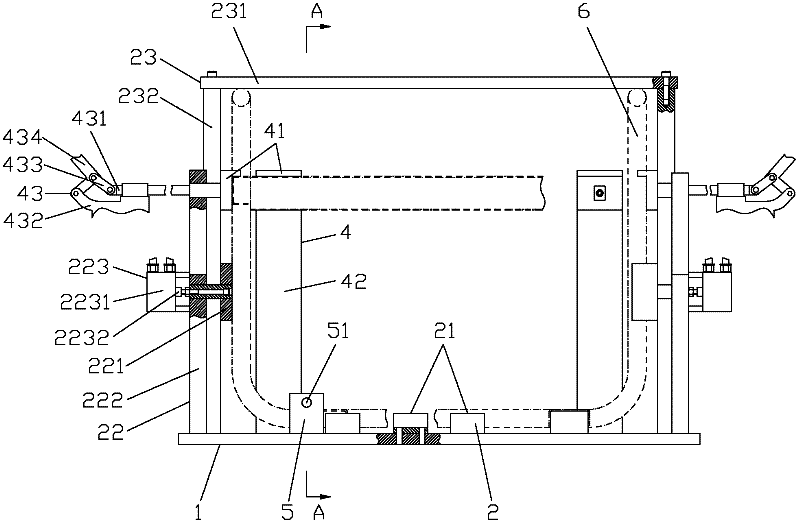
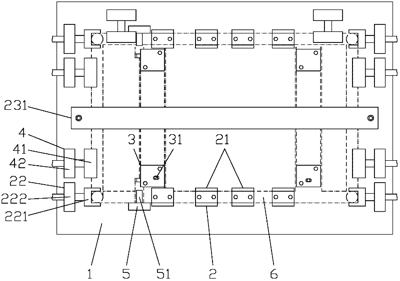
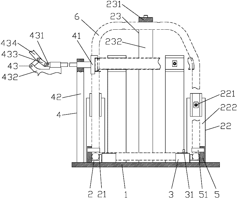
[0016] figure 1 It is the front view of the present invention, figure 2 It is a top view of the present invention, as shown in the figure: subject to the position shown in the figure, the engine frame welding tooling of this embodiment includes a fixed plate 1, a frame elbow positioning assembly 2, a bottom plate positioning block 3, and a beam positioning block 4 and the wheel axle seat positioning block 5, the frame elbow positioning assembly 2 includes concave limit sliders 21 distributed on the front and rear of the fixed plate 1, side positioning blocks distributed on the left and right sides of the fixed plate 1 Block 22 also includes hold-down device 23; Described concave positioning slide block 21 and side positioning block 22 are used to limit the horizontal direction degree of freedom of frame elbow 6, as shown in the figure: frame elbow 6 is made of metal tube Bending, including the bottom horizontal tube, vertical tube and top vertical tube, the bottom horizontal...


PUM


Abstract

The invention discloses a welding tool for an engine frame. The welding tool comprises a fixed plate, a frame bent pipe positioning component, a bottom plate positioning block, a cross beam positioning block and a wheel shaft seat positioning block, wherein the frame bent pipe positioning component comprises a concave limit sliding block, a lateral positioning block and a compaction device; the cross beam positioning block comprises a positioning sliding block, a supporting plate and a quick clamp; the positioning sliding block is connected to the fixed plate through the supporting plate; and the quick clamp is used for driving the positioning sliding block to slide along the horizontal direction. By the welding tool for the engine frame, a frame bent pipe, and a left bottom plate, a right bottom plate, a left cross beam, a right cross beam, a rear cross beam, a front wheel shaft seat and a rear wheel shaft seat which are required to be welded on the frame bent pipe can be accurately and reliably positioned, and the conditions that the frame cannot generate internal stress after being welded and being provided with other mechanical parts or equipment and cannot deform after being used for a long time are ensured; and a quick clamp structure is used for quick and accurate positioning, so that producing and processing efficiencies can be improved, the improvement on the quality of the processed frame is facilitated, and defective rates are reduced.

Description

technical field [0001] The invention relates to a frock fixture, in particular to a welding frock used for positioning the frame bend pipe constituting the engine frame and the reinforcement and connecting parts to be welded to the frame bend pipe. Background technique [0002] The engine frame is a bracket used to install and fix other mechanical parts and equipment. It connects various mechanical parts and equipment into a whole, which is easy to carry and use. [0003] It usually consists of rack bends bent from metal round pipes, connectors for connecting and fixing other mechanical parts and equipment, and reinforcements for strengthening the rack bend structure. Rack bends and connectors, reinforcements The parts are generally connected by welding. Usually, the operator relies on his work experience to ensure the shape and position error of the rack bend and the parts that need to be welded to the rack bend, and then perform spot welding and positioning, and then fully...

Claims


Application Information

Patent Timeline
Patent Type & Authority Applications(China)
IPC IPC(8): B23K37/04
Inventor 艾刚涂定国
Owner CHONGQING BEIBEI DISTRICT FENGHUO MACHINERY MFG
Learn More