Bidirectional lateral linkage and clamping mechanism

A clamping mechanism and linkage technology, applied in auxiliary devices, auxiliary welding equipment, welding/cutting auxiliary equipment, etc., can solve the problems of low work efficiency, high cost of control equipment, inconvenient maintenance, etc., and achieve high work efficiency and structure. Simple, easy-to-maintain effects

Inactive Publication Date: 2012-01-25
ANHUI JEE AUTOMATION EQUIP CO LTD
View PDF6 Cites 29 Cited by
  • Summary
  • Abstract
  • Description
  • Claims
  • Application Information

AI Technical Summary

Problems solved by technology

[0002] On the automobile welding line, the clamping tools are generally driven by a drive unit to achieve unilateral clamping movement. Conventionally, the cylinder is used as the drive, but this drive method has relatively low work efficiency.
There are also electrical controls to improve welding efficiency and realize the movement of multiple driven units driven by one drive unit, but the electrical components required for its structure are a luxury for some small and medium-sized fixtures, and the cost of corresponding control equipment is high. , maintenance is inconvenient

Method used


Image

  • Bidirectional lateral linkage and clamping mechanism
  • Bidirectional lateral linkage and clamping mechanism
  • Bidirectional lateral linkage and clamping mechanism

Examples


Embodiment Construction

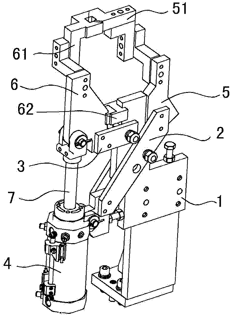
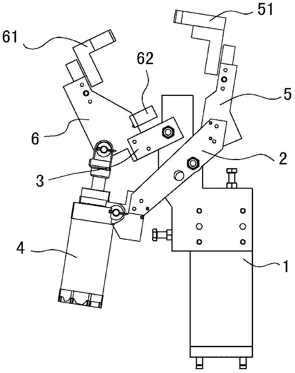
[0017] See figure 1 , figure 2 In this embodiment, the two-way side linkage clamping mechanism is to respectively hinge a rotatable hinge rod 2 and a rotatable connecting rod 3 on a fixed bracket 1, and the connecting rod 3 is located above the hinge rod 2; as a driving member The driving cylinder 4 is located on one side of the fixed bracket 1. The cylinder base 4 of the driving cylinder is hingedly mounted on one rod end of the hinge rod 2, and the other rod end of the hinge rod 2 is fixedly connected to the first rotating arm 5 and the first rotating arm 5. The oppositely arranged second rotating arm 6 is connected to the rod end of the connecting rod 3, and the rod end of the telescopic cylinder rod 7 in the driving cylinder is hinged with the second rotating arm 6.

[0018] The first rotating arm 5 and the second rotating arm 6 are driven by a bidirectional side linkage by a driving cylinder. When the cylinder rod 7 is contracted, the first rotating arm 5 and the second rota...


PUM


Abstract

The invention discloses a bidirectional lateral linkage and clamping mechanism, which is characterized in that: a rotatable hinging rod and a rotatable connecting rod are respectively hinged on a fixing bracket, and the connecting rod is positioned above the hinging rod; a driving cylinder as a driving member is positioned at one side of the fixing bracket, a cylinder seat of the driving cylinder is hinged at one rod end of the hinging rod, the other rod end of the hinging rod is fixedly connected with a first rotating arm, a second rotating arm which is opposite to the first rotating arm is fixedly connected to the rod end of the connecting rod, and the rod end of a telescopic cylinder rod in the driving cylinder is hinged with the second rotating arm. According to the invention, bidirectional lateral linkage drive to the first rotating arm and the second rotating arm by the driving cylinder is formed; and the bidirectional lateral linkage and clamping mechanism has the advantages of simple structure, easiness in maintenance and high working efficiency.

Description

Technical field [0001] The invention relates to a clamping tool applied to an automobile welding line, and more specifically to a clamping tool powered by a cylinder. Background technique [0002] In the automotive welding line, the clamping tools involved are generally driven by a driving unit to achieve unilateral clamping movement. Conventionally, the cylinder is the driving part, but this driving method has relatively low efficiency. Electric control is also used to improve welding efficiency and realize that one drive unit drives multiple driven units to move. However, the electrical components required for its structure are a luxury for some small and medium-sized fixtures, and the corresponding control equipment costs are high. , Maintenance is inconvenient. Summary of the invention [0003] In order to avoid the above-mentioned shortcomings of the prior art, the present invention provides a two-way side linkage clamping mechanism with simple structure, convenient use, con...

Claims


Application Information

Patent Timeline
Patent Type & Authority Applications(China)
IPC IPC(8): B23K37/04
Inventor 林巨广郑亮储大飞贾庆磊程浩胡育松邱峰马文明
Owner ANHUI JEE AUTOMATION EQUIP CO LTD
Why Eureka
Try Eureka