Array electrode cavity for jet electrodeposition

A spray electrodeposition and array electrode technology, applied in the direction of electrodes, can solve the problems of low spray electrodeposition processing efficiency and poor deposition quality, achieve uniform spray electrodeposition processing electric field and flow field, increase local concentration, and shorten spacing Effect

Active Publication Date: 2013-08-14
NANJING UNIV OF AERONAUTICS & ASTRONAUTICS
View PDF7 Cites 0 Cited by
  • Summary
  • Abstract
  • Description
  • Claims
  • Application Information

AI Technical Summary

Problems solved by technology

[0005] The purpose of the present invention is to solve the problems of low efficiency and poor deposition quality in the existing spray electrodeposition process, to provide a uniform electric field and flow field for spray electrodeposition process, to improve its current density and deposition speed, and to make it available Array electrode cavity for spray electrodeposition processing for electrodeposition processing of complex curved surfaces

Method used


Image

  • Array electrode cavity for jet electrodeposition
  • Array electrode cavity for jet electrodeposition
  • Array electrode cavity for jet electrodeposition

Examples


Embodiment Construction

[0025] The present invention will be further described below in conjunction with the accompanying drawings and embodiments.

[0026] Such as figure 1 , 2 , 3, 4 shown.

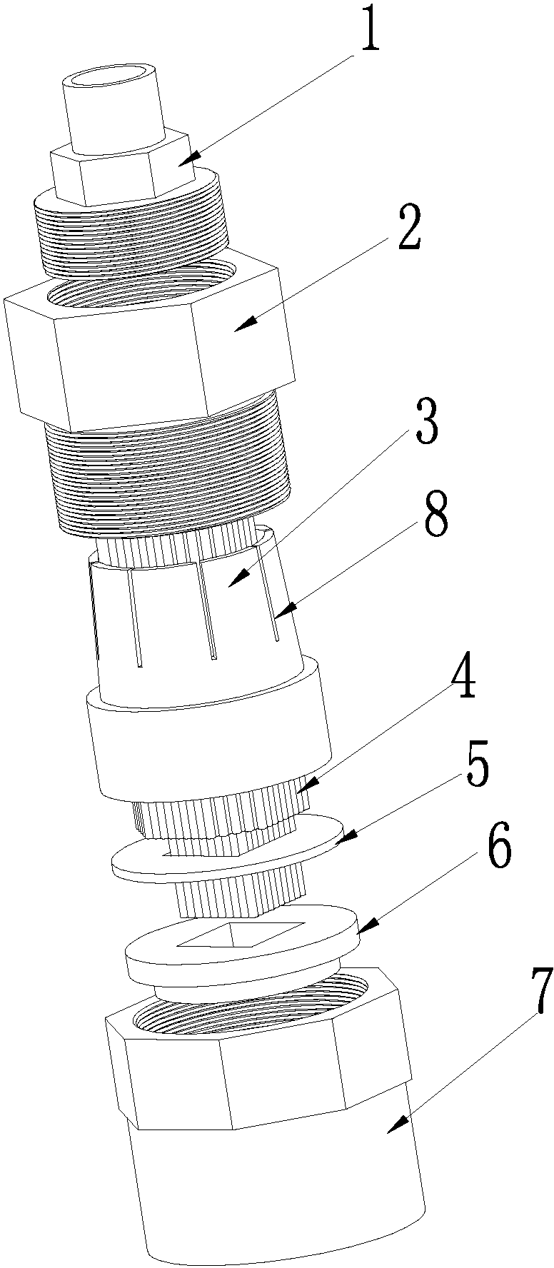
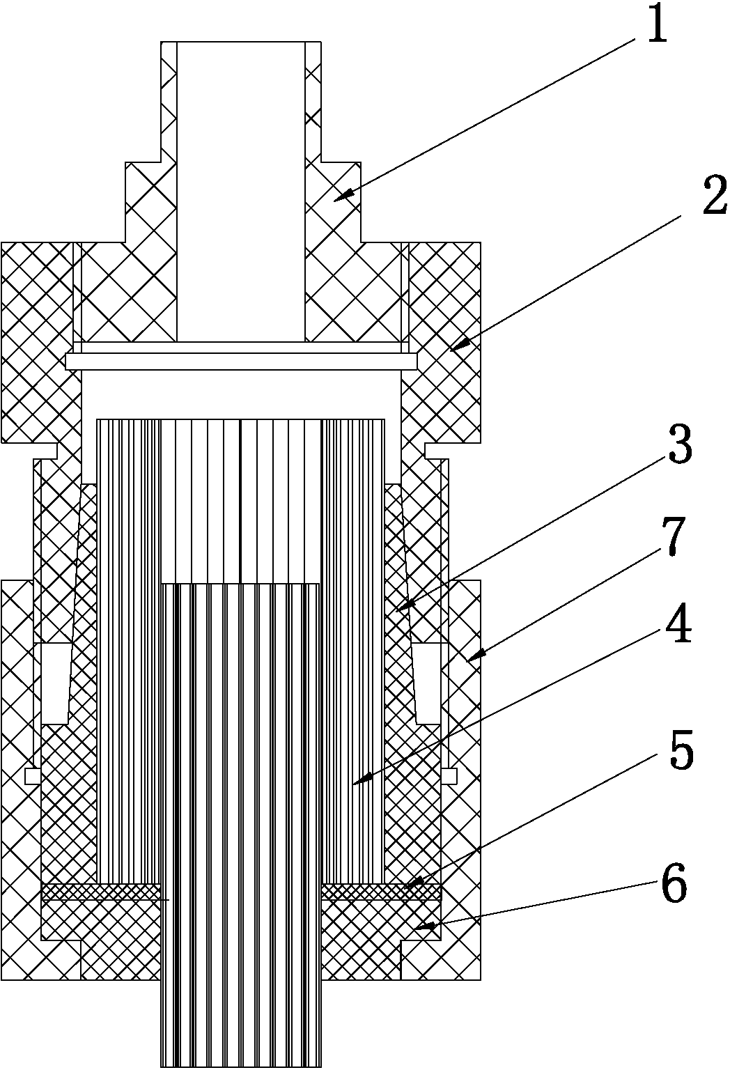
[0027] An array electrode cavity for spray electrodeposition processing, such as Figure 1 to Figure 2 As shown, it has a top cover 1, a cavity 2, a casing 3, an array electrode 4, a sealing ring 5, a rigid stop ring 6 and a tightening nut 7. Wherein: the top cover 1 is threadedly connected with the cavity 2, the sleeve 3 clamps the array electrode 4, the array electrode 4 is connected in series with the sealing ring 5 and the rigid stop ring 6, and the cavity 2 and the tightening nut 7 are connected by threads. By tightening the cavity 2 and tightening the nut 7, the top of the casing 3 is tightened, the clamping of the array electrode 4 and the compression of the sealing ring 5 and the rigid stop ring 6 are realized, and the array electrode is restricted by the stop ring 6 The protruding cross-sectio...


PUM


Abstract

The invention provides an array electrode cavity for jet electrodeposition. The electrode cavity is characterized by comprising a top cover, a cavity, a sleeve, an array electrode, a sealing ring, a rigid retainer ring and a tightening nut, wherein the top cover is in threaded connection with the cavity; the sleeve clamps the array electrode; the elastic sealing ring and the retainer ring are sequentially connected on the array electrode in series; the cavity and the nut are in threaded connection; and the top of the sleeve is tightened by screwing the cavity and the nut, so that the array electrode is clamped, the elastic sealing ring and the retainer ring are pressed tightly, and the shape of the extending section of the array electrode is limited by the retainer ring. According to the array electrode cavity, an array electrode nozzle with an arbitrary section shape and profile can be formed at the bottom of the electrode cavity, so that uniform electric field and flow field in jet electrodeposition processing can be acquired, the current density of electric deposition is improved, local concentration of metal ions is improved, oxidation in electrodeposition is avoided, and efficiency and quality of electrodeposition are finally improved. Processing of electrodeposition parts with special structures can be realized by designing array electrode cavities with different shapes and controlling conduction of the electrode.

Description

technical field [0001] The invention relates to the technical field of special processing, in particular to an electrodeposition technology, in particular to an array electrode chamber for spray electrodeposition processing. Background technique [0002] Due to the influence of concentration polarization, uneven electric field distribution and hydrogen evolution, traditional electrodeposition technology (electroforming and electroplating) often leads to low available current density and current efficiency, long processing time, poor uniformity of electrodeposited layer, and easy Defects such as pinholes, pitting, and burnt cast layer appear. Spray electrodeposition technology is to charge the electrolyte containing metal ions to the cathode at high speed under the control of the computer in the form of high-speed jet, and perform regional selective electrodeposition. [0003] The jet electrodeposition technology can effectively overcome some defects and limitations of the a...

Claims


Application Information

Patent Timeline
Patent Type & Authority Patents(China)
IPC IPC(8): C25D5/08C25D17/10
Inventor 沈理达邱明波高雪松王桂峰刘志东田宗军黄因慧
Owner NANJING UNIV OF AERONAUTICS & ASTRONAUTICS
Why Eureka
Try Eureka