Vacuum preloading consolidation method for duplex vacuum tube well of blowing filling soft soil
A vacuum tube well and vacuum tube technology, applied in soil protection, construction, infrastructure engineering, etc., can solve the problems of insignificant reinforcement effect, low transmission efficiency, and difficult drainage, etc., to achieve improved reinforcement effect, easier drainage, and improved transmission efficiency Effect
- Summary
- Abstract
- Description
- Claims
- Application Information
AI Technical Summary
Problems solved by technology
Method used
Image

Examples
Embodiment 1
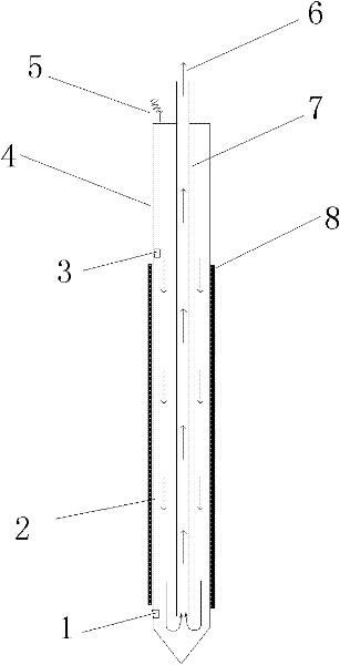
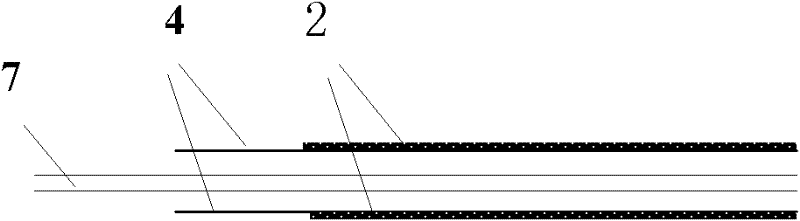
[0038] refer to figure 1 and figure 2 , a composite vacuum tube well vacuum preload reinforcement method for filling soft soil, using a composite vacuum tube well, the composite vacuum tube well includes an inner tube 7, an outer tube 4 and a filter membrane 2, the lower end of the outer tube 4 is closed, and the The upper end of the outer tube 4 is provided with a sealing head, and the inner tube passes through the sealing head and extends into the bottom of the inner cavity of the outer tube. The outer wall of the middle and lower part of the outer tube is covered with the filter membrane, and the tube wall of the outer tube where the filter membrane is located has a water-permeable hole; the inner tube is directly connected to the vacuum system, and the water in the outer tube is pumped away and a negative pressure is generated in the outer tube , in the early stage of reinforcement, intermittently turn on the vacuum pump to pump water, and reduce the water content of the...
Embodiment 2
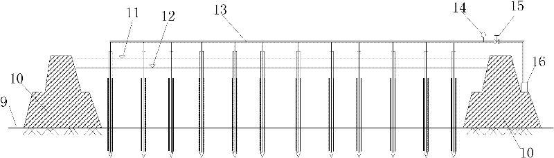
[0047] refer to image 3 and Figure 4 , In the present embodiment, the mud is blown and filled first, and then the vacuuming equipment is set. At this time use figure 2 The soft duplex vacuum tube well of design, outer pipe 4 is the corrugated filter pipe of diameter 5cm, and inner pipe 7 adopts the spring plastic hose of diameter 2cm or can vacuumize plastic hose. See layout diagram Figure 4 , the main implementation technical steps are as follows:
[0048] (1) Build the cofferdam first, then blow fill the soft soil in the cofferdam, and install the double vacuum corrugated filter pipe after the soft soil has settled down to a certain level due to its own weight.
[0049] (2) Connect the vacuum hose of the compound vacuum corrugated filter tube to the vacuum system.
[0050] (3) Complete the laying of geotextile and sealing mold.
[0051] (4) The vacuum pump is turned on intermittently before vacuuming, the main purpose is to extract the water in the soft double vacu...
PUM
| Property | Measurement | Unit |
|---|---|---|
| Diameter | aaaaa | aaaaa |
| Diameter | aaaaa | aaaaa |
Abstract
Description
Claims
Application Information
 - Generate Ideas
- Intellectual Property
- Life Sciences
- Materials
- Tech Scout
- Unparalleled Data Quality
- Higher Quality Content
- 60% Fewer Hallucinations
Browse by: Latest US Patents, China's latest patents, Technical Efficacy Thesaurus, Application Domain, Technology Topic, Popular Technical Reports.
© 2025 PatSnap. All rights reserved.Legal|Privacy policy|Modern Slavery Act Transparency Statement|Sitemap|About US| Contact US: help@patsnap.com