Lighting method and device of LED (light-emitting diode)
A technology of LED lighting and light-emitting devices, which is applied in the direction of lighting devices, components of lighting devices, cooling/heating devices of lighting devices, etc., and can solve problems such as inability to conduct heat through LEDs, reduce LED luminous efficiency, and low light utilization efficiency. To achieve the effect of improving heat dissipation, avoiding the reduction of LED luminous efficiency, and improving luminous efficiency
- Summary
- Abstract
- Description
- Claims
- Application Information
AI Technical Summary
Problems solved by technology
Method used
Image


Examples
Embodiment 1
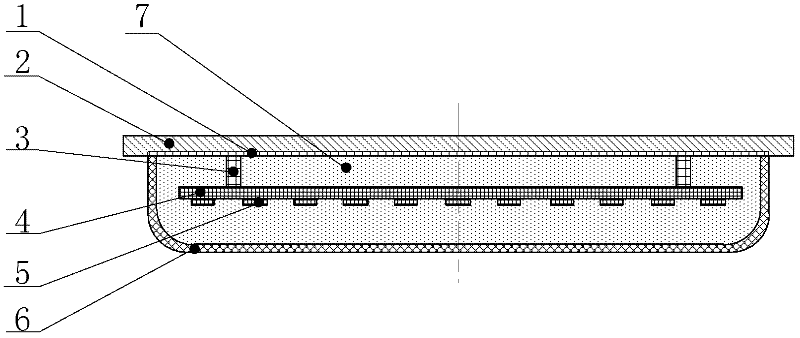
[0021] Example 1. The invention relates to an LED lighting and lighting method, in which the exposed LED chip without sealing glue is placed in the air in a transparent insulating heat-conducting fluid, so as to improve the luminous efficiency and heat-conducting effect of the LED chip and reduce light decay. Fix the LED chip 5 on the transparent support 4 without covering the sealing glue, the chip is exposed, the transparent support 4 is supported by the electrode support 3, and suspended in the transparent insulating heat transfer fluid 7 added with phosphor powder, after the LED chip 5 emits light, The phosphor powder irradiated into the transparent insulating thermal fluid 7 reflects the required spectrum and color. The transparent insulating heat-conducting fluid 7 is sealed in the space formed between the transparent cover 6 and the heat-conducting bottom plate 2. When the LED is heated during operation, the transparent insulating heat-conducting fluid 7 is heated to ge...
Embodiment 2
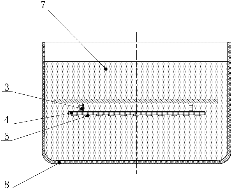
[0023] Example 2. The dimming method of the aforementioned LED lighting luminescence, such as figure 2 As shown, the LED light-emitting component composed of the aforementioned LED chip 5, transparent support 4, electrode support 3, metal reflective foil 1 and heat-conducting bottom plate 2 is suspended and immersed in a transparent insulating heat-conducting liquid 7 containing fluorescent powder. The transparent insulating thermal fluid 7 is placed in a transparent container 8 . Different luminescent effects can be obtained by configuring different phosphor powders in the transparent insulating thermal fluid. When configuring transparent insulating thermal fluid mixed with different phosphors, different luminous effects will be obtained. Since it is more convenient to configure transparent insulating heat-conducting fluids with different phosphors, the configuration of the liquid fluorescent lighting solution for LEDs is more economical and convenient than the existing so...
PUM
 Abstract
Description
Claims
Application Information
 - Generate Ideas
- Intellectual Property
- Life Sciences
- Materials
- Tech Scout
- Unparalleled Data Quality
- Higher Quality Content
- 60% Fewer Hallucinations
Browse by: Latest US Patents, China's latest patents, Technical Efficacy Thesaurus, Application Domain, Technology Topic, Popular Technical Reports.
© 2025 PatSnap. All rights reserved.Legal|Privacy policy|Modern Slavery Act Transparency Statement|Sitemap|About US| Contact US: help@patsnap.com