Heat pump industrial drying machine

A dryer and industrial technology, applied in the direction of dryers, drying, heat pumps, etc., can solve the problems of high cost of use, unstable working performance, low energy utilization rate, etc., and achieve the effect of convenient use and easy installation

Inactive Publication Date: 2012-01-25
SATURN CHANGZHOU TECH +1
View PDF2 Cites 18 Cited by
  • Summary
  • Abstract
  • Description
  • Claims
  • Application Information

AI Technical Summary

Problems solved by technology

Although the above-mentioned scheme has improved the performance to a certain extent, there are still...

Method used


Image

  • Heat pump industrial drying machine
  • Heat pump industrial drying machine
  • Heat pump industrial drying machine

Examples


Embodiment Construction

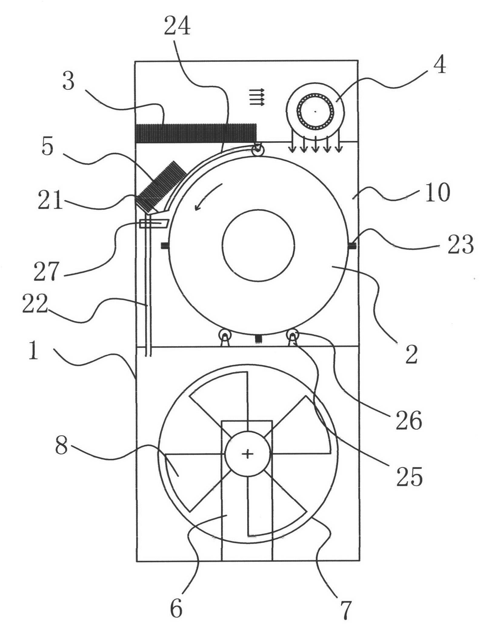
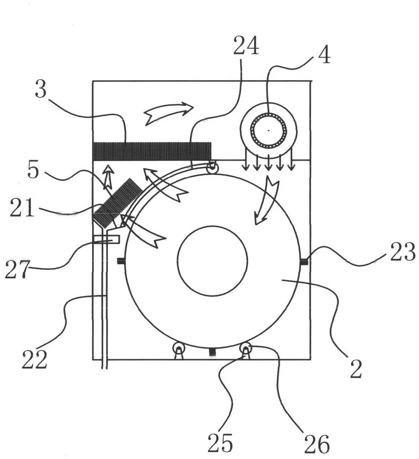
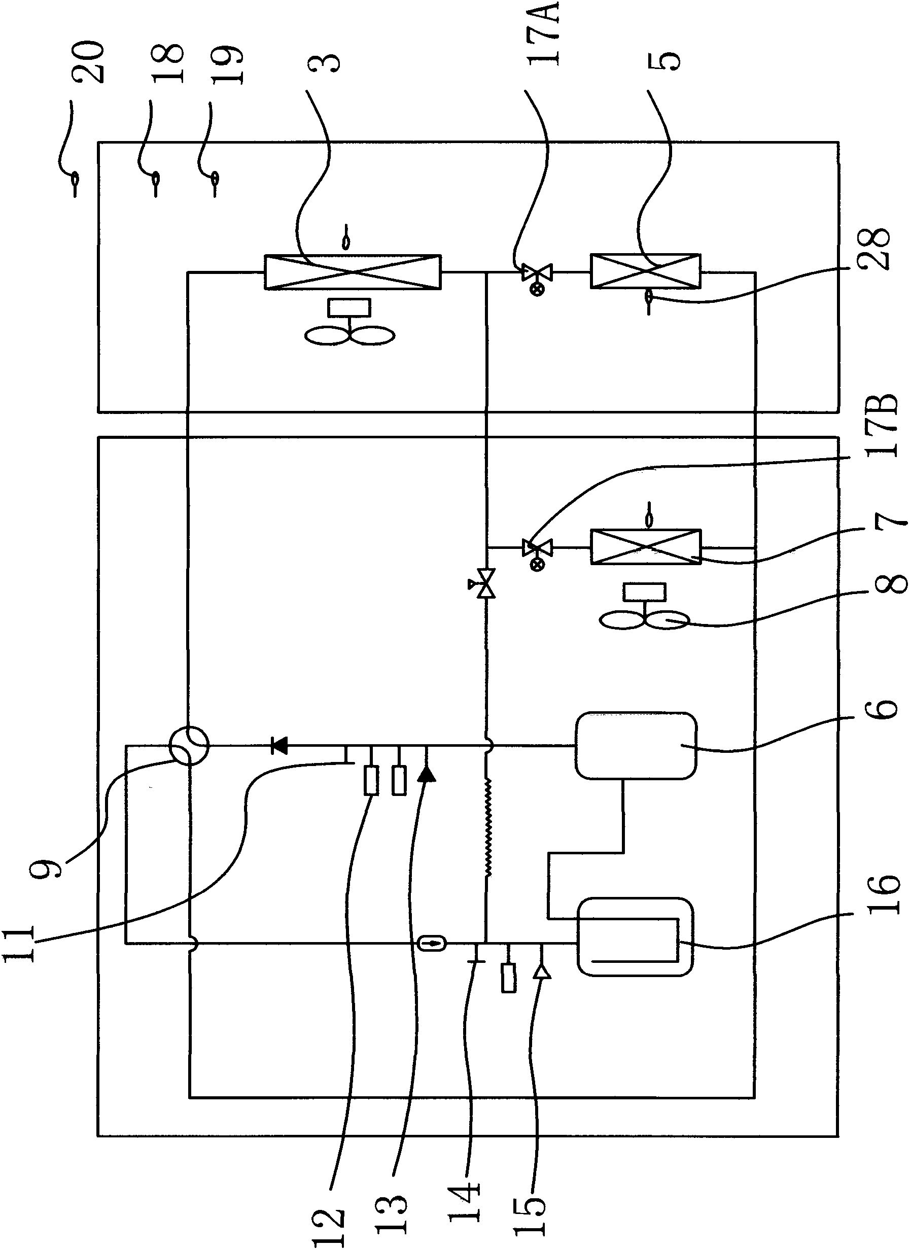
[0023] like figure 1 , 2 As shown in and 3, the heat pump industrial dryer includes a casing 1, and a sealed drying chamber 10 is arranged on the top of the casing 1. A cylindrical drum 2 is arranged inside the drying chamber 10, and the drum 2 is connected with a drum driving mechanism. The drying chamber 10 is provided with a condenser 3 which is located above the drum 2 and whose temperature is higher than the air temperature in the drying chamber 10. On one side of the condenser 3, a condenser 3 can be cooled and the hot air can be blown into the drum 2 to be heated. The circulation fan 4 on the heating and drying object. Below the condenser 3 is provided a dehumidifier 5 whose temperature is lower than the air temperature in the drying chamber 10, and below the dehumidifier 5 is provided a water collecting mechanism. The lower part of the box body 1 is provided with a heat pump system connected with the condenser 3 and the dehumidifier 5 . like figure 2 As mentioned...


PUM


Abstract

The invention belongs to the technical field of drying devices, and relates to a heat pump industrial drying machine, solving the technical problems of insufficient reasonable design in the prior art and the like. The drying machine comprises a box body; the upper part of the box body is provided with a sealed drying chamber; the drying chamber is internally provided with a cylindrical cylinder which is connected with a cylinder driving mechanism; the drying chamber is internally provided with a condenser which is positioned above the cylinder and the temperature is higher than the temperature in the drying chamber; one side of the condenser is provided with a circulation fan which can reduce the temperature of the condenser and blows hot air to a heated drying object in the cylinder; a dehumidifier the temperature of which is lower than that in the drying chamber is arranged below the condenser; a water collecting mechanism is arranged below the dehumidifier; and the lower part of the box body is provided with a heat pump system which is connected with the condenser and the humidifier. The drying machine has the advantages that the drying machine is easy to install, is convenient to use, is energy-saving, can dry rapidly, and adopts a nontraditional steam heating or electrical heating drying method, the using process is difficult to be influenced by the environmental humidity, and water steam is converted into cold condensation water and is exhausted in the treating process.

Description

technical field [0001] The invention belongs to the technical field of drying equipment, and relates to a dryer, in particular to a heat pump industrial dryer. Background technique [0002] There are two main types of heat sources for existing dryers: steam heating and electric heating. Due to environmental impact assessment requirements, coal-fired boilers are not allowed to be used in general cities, so steam sources are limited, so many dryer users who use steam as a heat source are often close to thermal power plants, chemical plants and other places with surplus steam, and these places are relatively remote from urban areas , so the use environment is greatly restricted. There are not many restrictions on the application of electric heating, but the biggest disadvantage of electric heating is that the cost is too high. The electric heating power of an ordinary 50Kg dryer is above 20KW, and the power consumption for one hour needs 20 degrees. Moreover, the price of indu...

Claims


Application Information

Patent Timeline
IPC IPC(8): F26B25/00F25B21/00F25B30/02F26B11/04B01D53/26
CPCY02B30/66Y02B30/00
Inventor 谢能作
Owner SATURN CHANGZHOU TECH
Why Eureka
Try Eureka