
Blade body sectional surface design method for die forging blade

A technology of airfoil profile and design method, applied in calculation, special data processing applications, instruments, etc., can solve the problem that there is no relevant report on CAD/CAM research work, the airfoil profile has not been optimized, and the airfoil shape has not been established. Face mathematical models and other issues to achieve the effect of shortening the product development and production cycle, realizing resource sharing and digital manufacturing, and having the effect of inheritance

Active Publication Date: 2013-05-01
SHENYANG LIMING AERO-ENGINE GROUP CORPORATION
View PDF0 Cites 0 Cited by
  • Summary
  • Abstract
  • Description
  • Claims
  • Application Information

AI Technical Summary

Problems solved by technology

[0002] At present, there is no relevant report on the CAD / CAM research work of precision forged blades with complex shapes in foreign countries.
Domestic Wuxi Blade Co., Ltd., Xi'an Antai Blade Technology Co., Ltd. and other units have developed the forming process and mold design CAD / CAM system suitable for their needs, but these software have not carried out secondary development for the design of precision forging blades
[0003] At present, die forging (including precision forging) blade airfoil profile and process design based on airfoil profile design have disadvantages such as poor precision, cumbersome design process and long design cycle.
The most important thing is that the design process is often carried out independently, which brings the following problems: 1) The repeatability of the design is poor, the design results of the previous design stage are not fully utilized, and the designer needs to repeatedly input and calculate a large amount of data, The design process is prone to errors; 2) The design workload is heavy, so that the designers cannot focus on the key issues of concern, making the design focus not prominent
3) Engineering changes are difficult, and often a small modification of the blade forging will cause a large change in the entire set of molds, requiring recalculation of many data
Especially for the airfoil part design of die forging (including precision forging) blades, the airfoil modeling still depends on repeatedly inputting the coordinate points of the airfoil surface to establish the airfoil model; there is no mathematical model of the airfoil surface; there is no After optimization processing, the profile is not smooth; the addition and placement of edge margins are still manually adjusted by the designer, which often brings large errors

Method used


Image

  • Blade body sectional surface design method for die forging blade
  • Blade body sectional surface design method for die forging blade
  • Blade body sectional surface design method for die forging blade

Examples


Embodiment 1

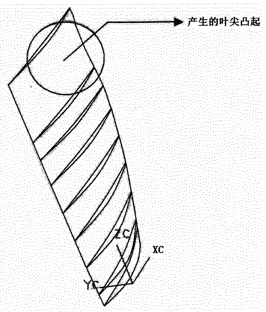
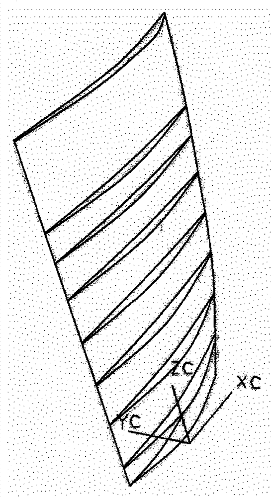
[0032] A die-forging blade airfoil profile design method, in which the die-forging blade airfoil profile design is sequentially performed according to the following requirements:

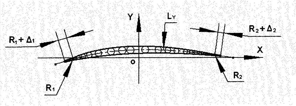
[0033] (1) First, according to the coordinate value of the airfoil surface point of the blade part, establish the mathematical model of the airfoil surface line; (2) according to the mathematical model, find the inscribed circle of the air inlet and exhaust sides of the airfoil; (3) ) Optimizing the edge radius or molding line to make the molding surface accurate and smooth; (4) Establishing a mathematical model of the blade airfoil forging on this basis, and adding the allowance.

[0034] The method for designing the airfoil profile of the die-forged blade also includes the following specific requirements:

[0035] In step (1), there are the following specific requirements: according to the coordinate values ​​of the airfoil surface points of the blade parts, the mathematical model of the airfoil s...


PUM


Abstract

The invention relates to a blade body sectional surface design method for a die forging blade. The blade body sectional surface design of the die forging blade is carried out according to the following requirements that: (1) firstly, a mathematical model of a blade body sectional surface line is built according to the coordinate values of the blade part blade body sectional surface points; (2) the inscribed circle of the air inlet and exhaust edges of the blade body is obtained according to the mathematical model; (3) the edge radius or the sectional line is optimized so that the sectional surface is precise and smooth; and (4) a blade forging element mathematical model is built on the basis, and in addition, the allowance increase is carried out. The method has the advantages that the design process is simple, the parametric design can be realized, the blade body sectional surface is smooth, the design model precision is high, and the like. The fast conversion and output process of the process files or parts, forging elements and the like can be realized, simultaneously, the resource sharing and the digital manufacture can be simultaneously realized, the design and manufacture period can be greatly shortened, the development process is accelerated, and the production efficiency is improved.

Description

technical field [0001] The invention relates to the surface design technology of die forging blade airfoil in the field of material forming engineering, and in particular provides a method for designing the airfoil shape of die forging blade. Background technique [0002] At present, there are no relevant reports abroad on CAD / CAM research work on precision forged blades with complex shapes. Domestic Wuxi Blade Co., Ltd., Xi'an Antai Blade Technology Co., Ltd. and other units have developed the forming process and mold design CAD / CAM system suitable for their needs, but these software have not carried out secondary development for the design of precision forging blades. [0003] At present, die forging (including precision forging) blade airfoil profile and process design based on airfoil profile design have disadvantages such as poor precision, cumbersome design process and long design cycle. The most important thing is that the design process is often carried out independ...

Claims


Application Information

Patent Timeline
Patent Type & Authority Patents(China)
IPC IPC(8): G06F17/50
Inventor 邰清安杨胜群崔树森李民史凤岭李治华孔祥伟
Owner SHENYANG LIMING AERO-ENGINE GROUP CORPORATION
Learn More