
Dynamic compensating device for feedback position of encoder and dynamic compensating method thereof

An encoder feedback and dynamic compensation technology, applied in motor control, electronic commutator, electrical components, etc., can solve the problem of position detection accuracy deterioration, sine wave signal phase difference error, sine signal and cosine signal size, phase and Center level error, etc.

Active Publication Date: 2012-01-25
DELTA ELECTRONICS INC
View PDF6 Cites 9 Cited by
  • Summary
  • Abstract
  • Description
  • Claims
  • Application Information

AI Technical Summary

Problems solved by technology

However, the sine wave signals of phase A and B will cause errors in the phase difference of the sine wave signals of the two phases due to assembly errors between the light-emitting components or light-receiving components, rotating bodies, or long-term changes and temperature changes, making The original sine signal and cosine signal may have size, phase and center level errors, so that the interpolated position obtained by the calculation is not completely linear (that is, there is a relative position error), resulting in poor position detection accuracy

Method used


Image

  • Dynamic compensating device for feedback position of encoder and dynamic compensating method thereof
  • Dynamic compensating device for feedback position of encoder and dynamic compensating method thereof
  • Dynamic compensating device for feedback position of encoder and dynamic compensating method thereof

Examples


Embodiment Construction

[0057] The detailed description and technical content of the present invention are described below with accompanying drawings. However, the attached drawings are provided for reference and illustration only, and are not intended to limit the present invention.

[0058] Hereby, the technical content and detailed description of the present invention are described as follows in conjunction with the drawings:

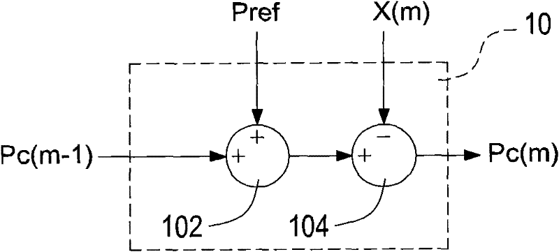
[0059] See figure 1 , is a schematic block diagram of the dynamic compensation device for encoder feedback position of the present invention. A dynamic compensation device for the feedback position of an encoder is applied to a servo control system when the driver drives a motor to rotate at a constant speed. The driver detects the feedback position of the encoder and provides position error compensation for the feedback position. The dynamic compensation device for encoder feedback position mainly includes a compensation amount calculation unit 10 , a position interval ju...


PUM


Abstract

The invention relates to a dynamic compensating device for a feedback position of an encoder and a dynamic compensating method thereof. When a driver which is applied to a servo control system drives a motor to rotate at a constant speed, the driver detects the feedback position of the encoder and provides the compensation for a position error for the feedback position. Firstly, a compensation dosage of the feedback position of the encoder is calculated by a compensation dosage calculating unit, and then a position area where the compensation dosage locates is determined by a position area determining unit, and lastly the compensation dosage is corrected in different weight modes by a compensation dosage correcting unit, thereby calculating the compensation dosage through the accumulation in an iteration mode, causing an error between the feedback position of the encoder detected by the driver and an ideal position to be in a permissible range, and increasing the accuracy of the encoder for dynamically compensating the feedback position.

Description

technical field [0001] The invention relates to a compensation device for an encoder feedback position and a dynamic compensation method thereof, in particular to a dynamic compensation device for an encoder feedback position and a dynamic compensation method thereof. Background technique [0002] With the continuous advancement of science and technology, precise, fast, high-resolution and high-bandwidth system requirements are the goals pursued by the industry today. Speed ​​or position control is required in many products or equipment that use motors, such as optical drives, printers, X-Y platforms, robotic arms, and semiconductor process equipment...etc. If the control system can control the speed and position quite accurately and precisely, the quality and characteristics of the products or equipment produced will be better. It can be seen that the impact of precision positioning control on the development of today's technology is becoming more and more important. . ...

Claims


Application Information

Patent Timeline
IPC IPC(8): H02P6/16H02P29/00
Inventor 周家至
Owner DELTA ELECTRONICS INC
Learn More