
Tester control method in automatic testing system

A technology of automated testing and control methods, applied in transmission systems, digital transmission systems, data exchange networks, etc., can solve the problems of test instrument utilization, unreasonable enterprises, and high cost, so as to reduce manual intervention and reduce costs investment and the effect of improving execution efficiency

Active Publication Date: 2012-01-25
MAIPU COMM TECH CO LTD
View PDF3 Cites 24 Cited by
  • Summary
  • Abstract
  • Description
  • Claims
  • Application Information

AI Technical Summary

Problems solved by technology

The current situation is that PCs can no longer meet the test requirements in terms of flexibility or other performance, and it is often necessary to introduce more powerful third-party special test instruments into the test system, such as Spirent's TestCenter and Smartbits and other products
[0005] It is not easy to incorporate third-party dedicated test instruments into the automated testing of enterprises, but compatibility and cost issues need to be considered
At present, there are mainly two processing methods: 1. Directly introduce a complete set of automated testing solutions provided by test instrument suppliers. This method has the following disadvantages: the capital investment of software and auxiliary equipment is very large, and it cannot be compared with existing testing methods For system integration, either run two systems, which will increase maintenance costs, or overthrow your existing automation system and redo scripts, which will cost even more; 2. Use some control APIs (application programming interfaces) provided by test instruments Expanding on some test platforms also faces a problem, that is, the utilization rate of test instruments. A test instrument can cost tens of millions. If the test instruments cannot be effectively used, it will be a very huge task. In addition, whether the test instrument can be flexibly applied in the existing automation platform to achieve the effect of automation is also a big problem. If more manual intervention is added to the automated test process due to the introduction of the test instrument, it will be difficult for the enterprise. is also very unreasonable

Method used


Image

  • Tester control method in automatic testing system
  • Tester control method in automatic testing system
  • Tester control method in automatic testing system

Examples


Embodiment Construction

[0035] The present invention will be further described below in conjunction with the accompanying drawings and embodiments.

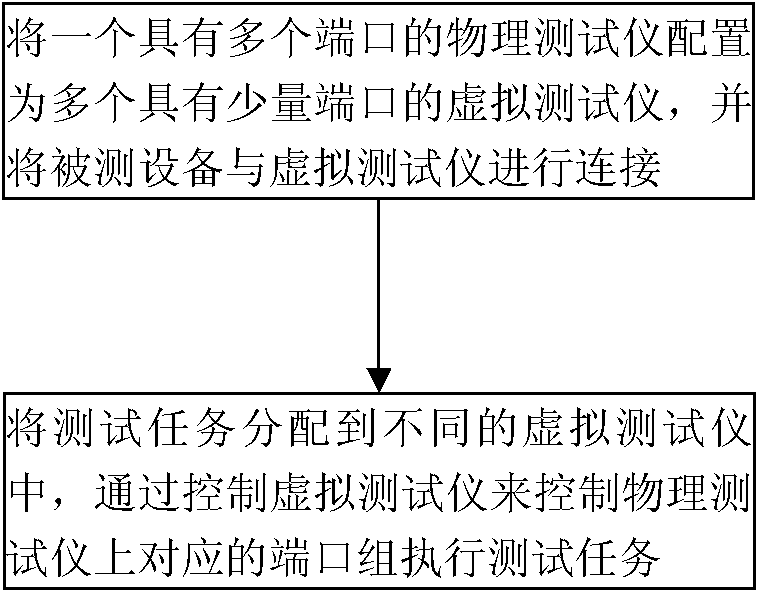
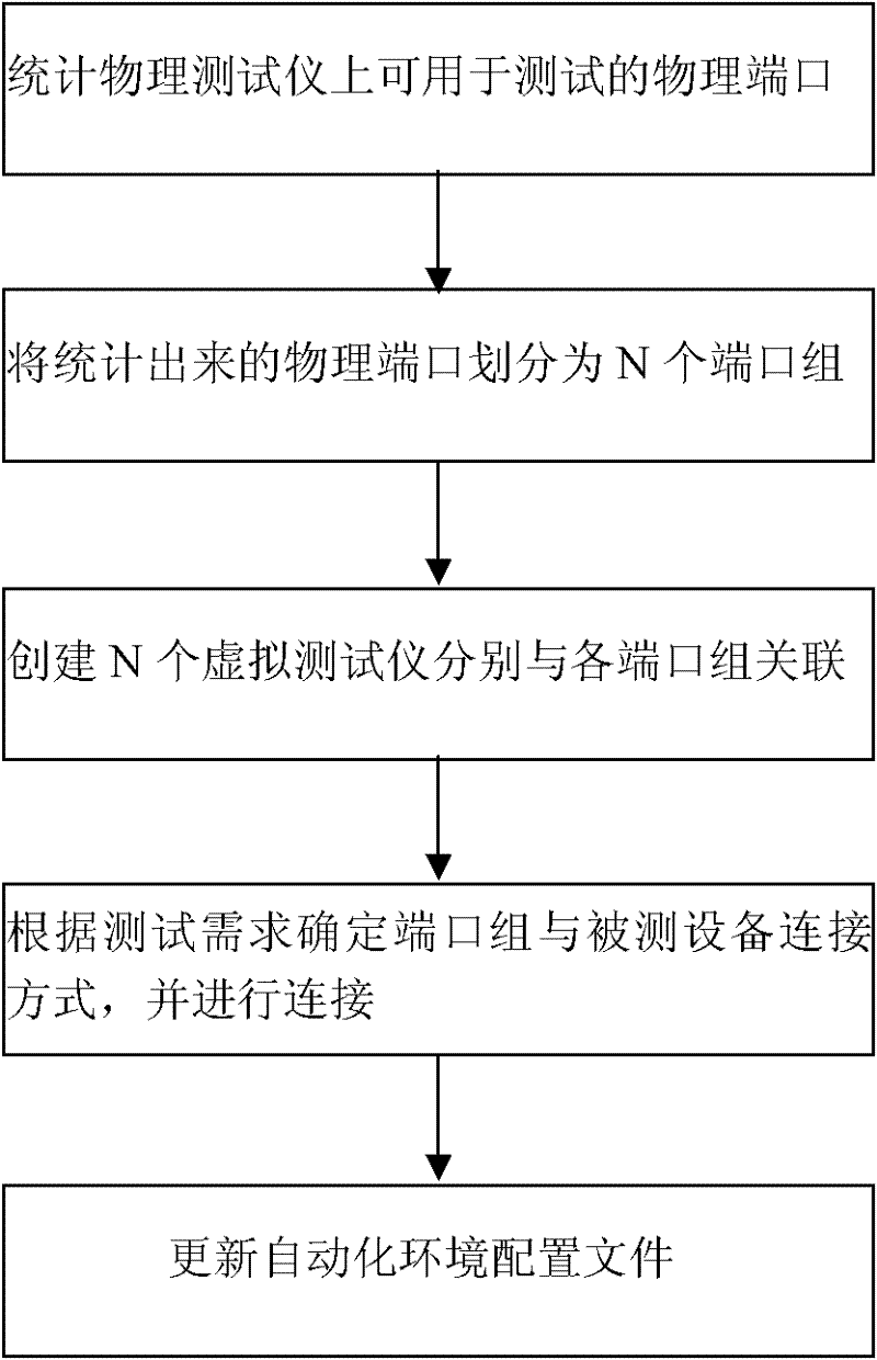
[0036] The invention discloses a tester control method in an automatic test system, which maximizes the utilization rate of the tester, fully considers the flexibility of the use of the tester, and minimizes manual intervention in the automatic test process. The main means of implementation are: group the ports on the physical tester, create virtual testers with the same number of groups to associate with each port group, and control the corresponding port groups on the physical tester to perform tests by controlling the virtual tester Tasks, so that multiple test tasks can be executed independently and in parallel, so that the expensive tester resources can be fully utilized in the automated testing process, and the cost of automated testing is also reduced; at the same time, the port group on the tester is based on Test requirements Choose the way of ...


PUM


Abstract

The invention relates to an automatic testing technology in the field of data communication, and discloses a tester control method in an automatic testing system, which furthest improves the utilization rate of a tester, fully considers the flexibility of using the tester and reduces manual intervention works in an automatic testing process as far as possible. The technical scheme is characterized by comprising the steps of: grouping ports on a physical tester, creating same grouping quantity of virtual testers for associating with all port groups, and controlling corresponding port groups on the physical tester for executing a test task by controlling the virtual testers. The invention is suitable for automatic test of a communication device.

Description

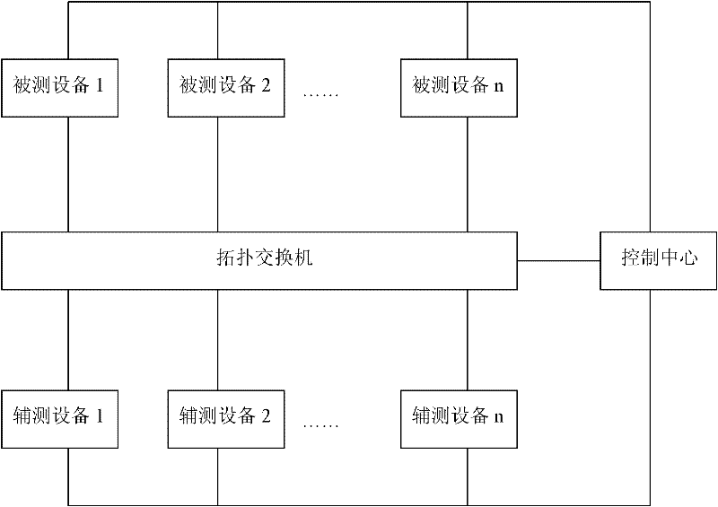
technical field [0001] The invention relates to an automatic test technology in the field of data communication, in particular to a tester control method in an automatic test system. Background technique [0002] At present, the wide application of automated testing technology in the field of data communication has largely released the repetitive workload of testers. At the same time, automated testing technology has also made great contributions to reducing product development costs, shortening development cycles, and ensuring product quality. [0003] With the development of automated testing technology, the test content covered by automated testing has been continuously enriched and expanded, making more and more devices under test and auxiliary testing equipment used in automated testing technology. At present, a typical automated test system such as figure 1 As shown: the entire test system can be divided into two parts: the control network and the test network. The te...

Claims


Application Information

Patent Timeline
IPC IPC(8): H04L12/26
Inventor 郭静
Owner MAIPU COMM TECH CO LTD
Learn More