Protection circuit for preventing LED from impact

An impact protection, LED driver technology, applied in the direction of electric lamp circuit layout, electric light source, electrical components, etc., can solve the problems of large saturation voltage drop of bipolar triodes, not in line with the high efficiency and energy saving of LED lamps, and not suitable for mass production, etc. Achieve the effect of fast transient response, small voltage drop, and prevention of breakdown

Active Publication Date: 2012-01-25
SELF ELECTRONICS CO LTD
View PDF6 Cites 13 Cited by
  • Summary
  • Abstract
  • Description
  • Claims
  • Application Information

AI Technical Summary

Problems solved by technology

The above patent can ensure that when a certain LED in the LED light string fails and opens the circuit, the PLED can be turned on instantly to ensure the normal operation of the LED lamp. However, the above patent needs to connect polymer light-emitting diodes in series in the circuit. Light-emitting diodes (PLEDs) have not yet been industrialized on a large scale, and the price of raw materials is very expensive, which is not suitable for large-scale production
Therefore, the current limiting circuit in the prior art is generally implemented by bipolar transistors, but the saturation voltage drop of the bipolar transistors is relatively large when the LED lamp needs a larger drive current. A lot of loss, not in line with the application concept of LED lamps with high efficiency and energy saving

Method used


Image

  • Protection circuit for preventing LED from impact
  • Protection circuit for preventing LED from impact
  • Protection circuit for preventing LED from impact

Examples


Embodiment Construction

[0023] The present invention will be further described in detail below in conjunction with the accompanying drawings and embodiments.

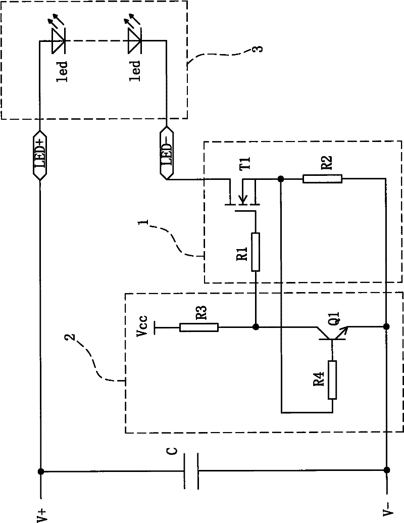
[0024] Such as figure 1 As shown, it is the basic circuit schematic diagram of the LED impact protection circuit of this embodiment. The impact protection circuit includes a discharge capacitor C, an LED load 3, a current limiting circuit 1 and a control circuit 2, wherein the two ends of the discharge capacitor C are connected in parallel On the positive pole V+ of the DC power supply and the negative pole V- of the DC power supply of the LED driver, the LED load 3 is connected in parallel to the positive pole LED+ of the output power supply of the LED driver and the negative pole LED- of the output power supply; the LED load in this embodiment is turned off or turned on by a Controlled by the controllable switch K, the LED load can be composed of a single or multiple LED lamps in series, one end of the controllable switch K is connected to t...


PUM


Abstract

The invention relates to a protection circuit for preventing an LED from an impact. The protection circuit comprises a discharging capacitance and an LED load. Besides, the protection circuit is characterized in that: the protection circuit also comprises a field effect transistor, a first resistor, a second resistor, a first triode, a third resistor, and a fourth resistor; a resistance value of the second resistor is greater than or equal to a ratio of a threshold voltage of the first triode to a maximum breakdown current of the LED load; a drain electrode of the field effect transistor is connected with an output power supply cathode of an LED driver; one path of a source electrode of the field effect transistor is connected with a direct current power supply cathode of the LED driver through the second resistance; and the other path of the source electrode of the field effect transistor is connected with a base electrode of the first triode through the fourth resistance; an emitter electrode of the first triode is connected with the output power supply cathode of the LED driver; and one path of a grid of the field effect transistor is connected with a collector electrode of the first triode through the first resistance and the other path of the grid of the field effect transistor is connected with a direct current voltage through the third resistance. According to the invention, a low voltage field effect transistor is employed to carry out current limitation, so that a response speed of a whole circuit is fast and circuit power consumption is low; besides, an impact current from an LED driving power supply on a back stage LED load can be effectively inhibited as well as service life of the LED load can be prolonged.

Description

technical field [0001] The invention relates to an LED protection circuit, in particular to an LED impact protection circuit. Background technique [0002] LED lights (light-emitting diodes) are a new type of light source with energy saving, environmental protection and high luminous efficiency. However, because the forward dynamic resistance of LED is very small, it is impossible to directly supply power to LED with a voltage source, otherwise, the voltage fluctuation will increase slightly. , the current will increase rapidly, which will easily cause the LED to burn out. [0003] At present, high-power LED lamps are usually driven by constant current, and the steady-state output voltage of the constant-current driver varies with the number of LEDs connected to the output terminal. In lighting applications, when the driver is unloaded, the output voltage usually reaches the maximum value; if the user connects a switch between the output terminal of the driver and the LED l...

Claims


Application Information

Patent Timeline
Patent Type & Authority Applications(China)
IPC IPC(8): H05B37/02
CPCH05B37/02H05B45/395Y02B20/30H05B45/54
Inventor 鞠耀武汪彪潘黄锋林万炯
Owner SELF ELECTRONICS CO LTD
Why Eureka
Try Eureka