Sanitary device
A sanitation equipment and water tank technology, applied in the field of sanitation equipment, can solve the problems of multiple cleaning of the mop, and achieve the effect of avoiding excessive humidity and reducing the frequency of cleaning
- Summary
- Abstract
- Description
- Claims
- Application Information
AI Technical Summary
Problems solved by technology
Method used
Image

Examples
Embodiment 1
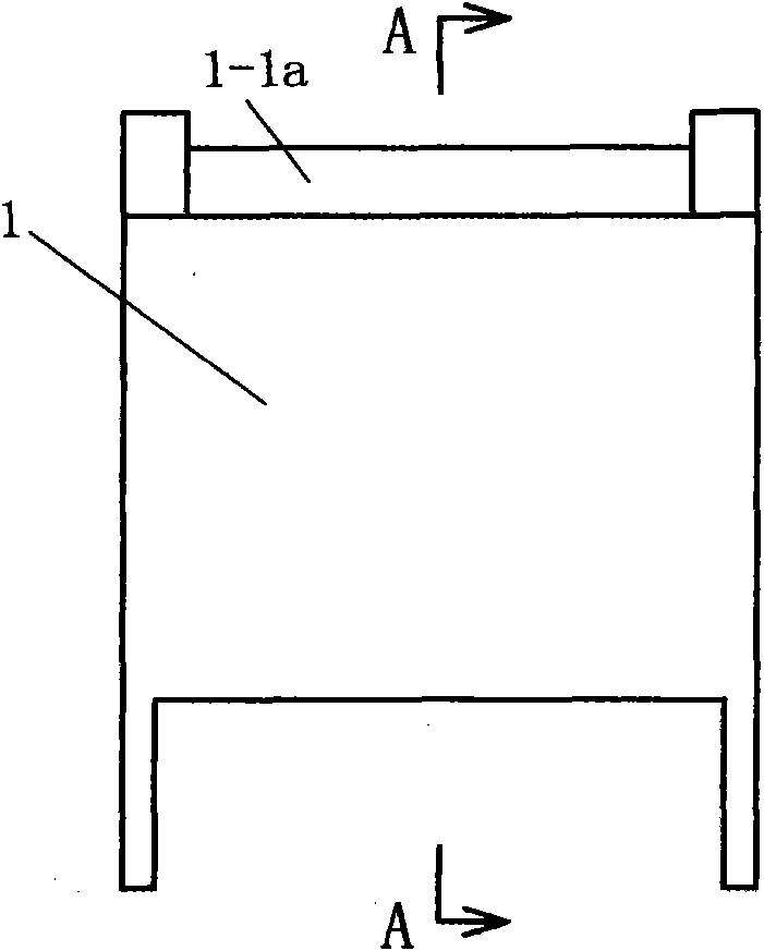
[0052] A sanitation device in the first embodiment includes: a water tank 1 filled with water 11, a lower roller 7, an upper roller 10, a water squeezing body 9, a cleaning belt 6, and a handle 12; the description and explanation are given below.
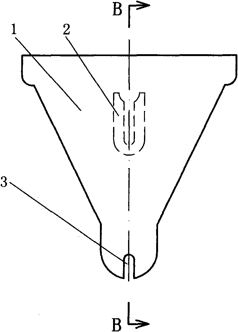
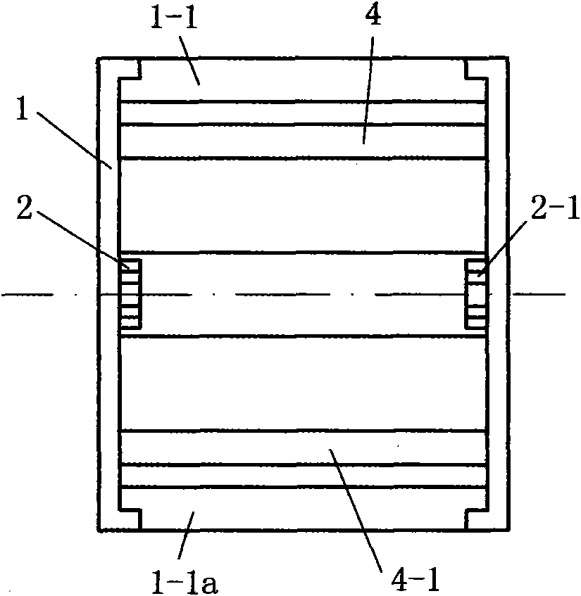
[0053] Water tank 1 in the present embodiment, see Figure 1 to Figure 7 . figure 1 It is the front view of the water tank in Embodiment 1; figure 2 yes figure 1 left view of image 3 yes figure 1 top view of Figure 4 yes figure 1 bottom view of Figure 5 yes figure 1 A-A sectional view of A-A; Figure 6 yes figure 2 B-B direction sectional view; Figure 7 It is a partial three-dimensional schematic diagram, which expresses the situation that the bearing body and the water tank are manufactured as one. The water tank 1 has four peripheral walls and a bottom wall, and the water tank 1 is open upwards; the four peripheral walls are respectively the left wall, the right wall, the front wall and the rear wall; figure 1 Lo...
Embodiment 2
[0069] combine figure 2 ,illustrate
[0070] In this embodiment, the inventive sanitary equipment introduced in Embodiment 1 is used.
[0071] Before use, the tension of the cleaning endless belt 6 can be adjusted by loosening the screws on the mounting block 8, and then tightening the screws and fixing when the tension of the cleaning endless belt 6 is adjusted to a suitable degree.
[0072] Then tap water is put into the water tank 1, and the water height is about 2 / 3rds of the water tank 1 height.
[0073] Then use as Figure 15 , Figure 16 Inventions shown for sanitation, cleaning grounds.
[0074] When the invention sanitary equipment was pushed forward, the cleaning ring belt 6 was rotated in a positive direction, as Figure 17 Shown, now lower roller 7 is also driven by the friction of cleaning endless belt 6, and rotates. Because the cleaning belt 6 rotates in the positive direction, the dirt on the ground is stuck by the cleaning belt 6 and brought into the wa...
Embodiment 3
[0077] In this embodiment, the water tank 1 in the sanitary equipment of the present invention also has a tank cover. The two types of covers are described below.
[0078] 1. The first type of tank cover: the tank cover is in the shape of a flat plate, and a buckle structure is provided correspondingly on the edge of the flat plate and the upward edge of the water tank 1.
[0079] Before mopping the field, remove the tank cover as a whole, inject tap water into the water tank 1, and then close the tank cover to mop the site; after mopping, remove the tank cover as a whole and pour out the dirty water in the water tank 1 Then rinse in clean tap water. Taking off the box cover and installing the box cover is realized by the user by toggling the buckle structure.
[0080] 2. The second type of tank cover: the tank cover is in the shape of a flat plate, one side of which is connected to the upward facing edge of the water tank 1 in a rotational connection, and the other side is ...
PUM
 Abstract
Description
Claims
Application Information
 - R&D
- Intellectual Property
- Life Sciences
- Materials
- Tech Scout
- Unparalleled Data Quality
- Higher Quality Content
- 60% Fewer Hallucinations
Browse by: Latest US Patents, China's latest patents, Technical Efficacy Thesaurus, Application Domain, Technology Topic, Popular Technical Reports.
© 2025 PatSnap. All rights reserved.Legal|Privacy policy|Modern Slavery Act Transparency Statement|Sitemap|About US| Contact US: help@patsnap.com