Polishing machine

A polishing machine, polishing pad technology, applied in the direction of grinding machine, grinding/polishing equipment, portable grinding machine, etc. The effect of low work cost, reduced floor space, and reduced friction injury

Inactive Publication Date: 2012-02-01
樊超
View PDF10 Cites 2 Cited by
  • Summary
  • Abstract
  • Description
  • Claims
  • Application Information

AI Technical Summary

Problems solved by technology

[0002] The traditional polishing machine adopts a horizontal design and has a complex structure. Generally, multi-cylinders and multi-machines are used to meet the brightness requirements of the material. For this polishing machine, the friction cloth must be replaced for hundreds of tons, and the iron net must be replaced for thousands of tons. The friction principle between the friction cloth, the material and the iron net is used to make the material rub between the friction cloth and the iron net. The disadvantage of the traditional grinder is that it occupies a large area, increases power consumption and crushing, and increases the cost. It is labor-intensive, labor-intensive, and costly, and the method of rubbing the material between the friction cloth and the iron net will make the material prone to scratches, cracks, and breakage during the friction process.

Method used


Image

  • Polishing machine
  • Polishing machine
  • Polishing machine

Examples


Embodiment Construction

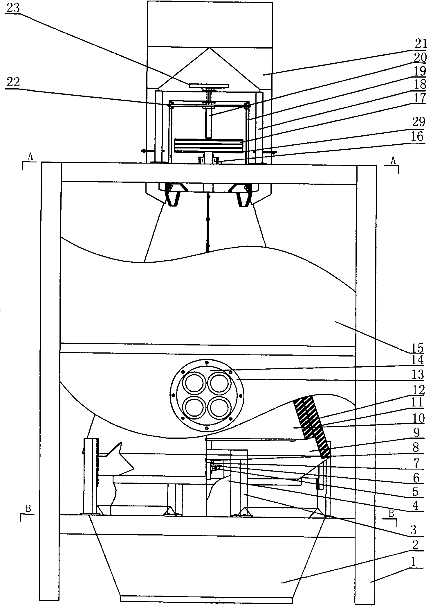
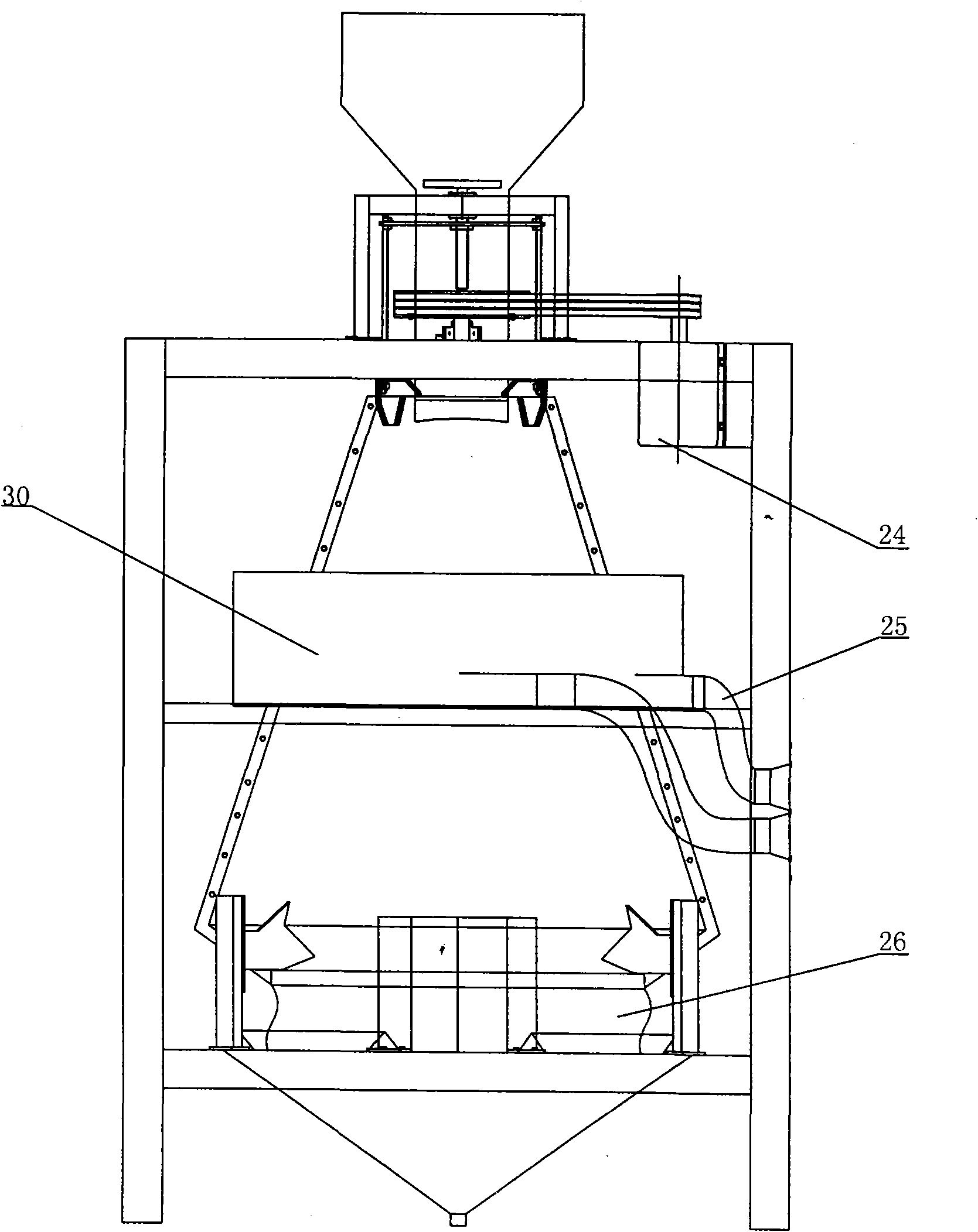
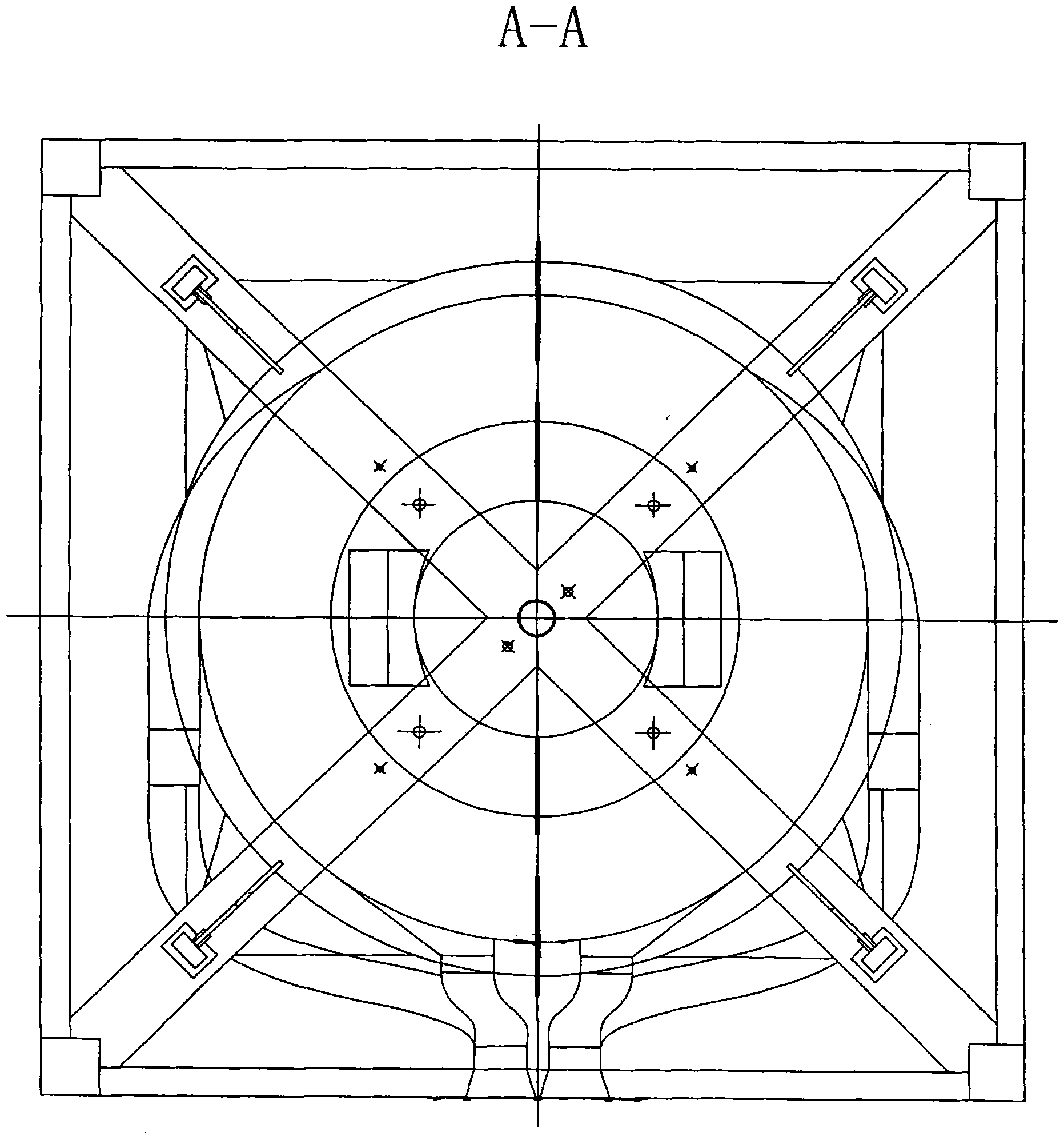
[0031] Such as Figure 1 to Figure 6 As shown, the polishing machine includes a frame 1, a lower hopper 2, a support frame 3, a baffle plate 4, a rolling ball bearing 5, a bearing seat 6, a thrust bearing 7, a transmission shaft 8, a polishing sleeve, an outer casing polishing pad 11, Inner sleeve polishing pad 12, vent flange 13, vent panel 14, cover plate 15, rolling ball bearing 16, V-belt 17, adjustment frame 18, screw 19, screw 20, hopper 21, adjustment plate 22, hand Wheel 23, motor 24, exhaust pipe 25, screen 26, flange interface 27, small round hole 28, V-belt pulley 29, exhaust fan 30, motor 24 and lower hopper 2 are installed on the frame 1, and the sleeve is polished It includes an outer polishing sleeve 9 and an inner polishing sleeve 10, the inner polishing sleeve 10 is welded on the transmission shaft 8, the outer polishing sleeve 9 is set on the outside of the inner polishing sleeve 10, and the outer polishing sleeve 9 The inside is inlaid with a cowhide leathe...


PUM


Abstract

The invention discloses a polishing machine, which comprises a frame, a transmission shaft, a motor, an upper hopper, a lower hopper and polishing sleeves, wherein the motor and the lower hopper are arranged on the frame; the polishing sleeves comprise an outer polishing sleeve and an inner polishing sleeve; the inner polishing sleeve is welded to the transmission shaft; the outer polishing sleeve is sleeved outside the inner polishing sleeve; the inner part of the outer polishing sleeve and the outer part of the inner polishing sleeve are provided with an outer sleeve polishing cushion and an inner sleeve polishing cushion respectively; the outer polishing sleeve consists of two half sleeves; the tops of the half sleeves of the outer polishing sleeve are provided with a lifting lug; the lifting lug is connected to a screw through a bolt; the upper part of the screw is connected to an adjusting plate through a bolt; the middle part of the adjusting plate is welded with a nut which is connected with the screw; the upper part of the screw is provided with a groove which is clamped on a circular hole part in the middle of an adjusting frame; and the top of the screw is provided with a hand wheel. The polishing machine has the advantages of guaranteeing that the material is not damaged, along with good dust removal effect for the material, low single-machine working cost, long service life, convenience in replacement, small size and less space.

Description

technical field [0001] The invention relates to a polishing machine. Background technique [0002] The traditional polishing machine adopts a horizontal design and has a complex structure. Generally, multi-cylinders and multi-machines are used to meet the brightness requirements of the material. For this polishing machine, the friction cloth must be replaced for hundreds of tons, and the iron net must be replaced for thousands of tons. The friction principle between the friction cloth, the material and the iron net is used to make the material rub between the friction cloth and the iron net. The disadvantage of the traditional grinder is that it occupies a large area, increases power consumption and crushing, and increases the cost. It is labor-intensive, labor-intensive, and costly, and the material is rubbed between the friction cloth and the iron net, which will make the material easy to be scratched, broken, and broken during the friction process. Contents of the inven...

Claims


Application Information

Patent Timeline
Patent Type & Authority Applications(China)
IPC IPC(8): B24B23/02
Inventor 樊超
Owner 樊超
Why Eureka
Try Eureka