
H-shaped power chassis with ground clearance adjusting function

A power chassis and functional technology, applied in the field of vehicle engineering, can solve problems such as easy slipping of driving wheels, inability to drive vehicles, complex all-wheel drive structure, etc., and achieve improved ride comfort and passability, improved passability, and good road conditions Effect

Inactive Publication Date: 2012-02-01
BEIHANG UNIV
View PDF4 Cites 4 Cited by
  • Summary
  • Abstract
  • Description
  • Claims
  • Application Information

AI Technical Summary

Problems solved by technology

Its disadvantages are: because the front wheels are responsible for steering and driving at the same time, the high-speed stability is poor, the driving wheel is easy to slip when going uphill, and it is easy to overturn when going downhill at high speed
The disadvantages of this type of drive are: the heavy load on the rear axle makes the car have a tendency to over-steer, the adhesion of the front wheels is small, the steering is unstable at high speeds, and the assembly and manufacturing costs are higher compared to front-wheel drive, and more faults, relatively small indoor space, etc.
However, the structure of all-wheel drive is complicated, the cost is high, the fuel consumption is large when driving on a good road, and the wear and tear of tires and parts is large.
[0007] For the above three driving modes, when one side of the wheel slips, due to the existence of the differential, the slipping wheel turns faster and faster, and the other side turns slower and slower, causing the drive axle to lose its driving force, resulting in the vehicle being unable to drive

Method used


Image

  • H-shaped power chassis with ground clearance adjusting function
  • H-shaped power chassis with ground clearance adjusting function
  • H-shaped power chassis with ground clearance adjusting function

Examples


Embodiment Construction

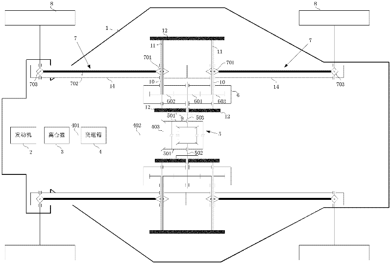
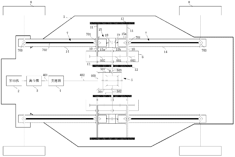
[0037] A kind of H type power chassis of the present invention, comprises chassis 1 and the engine 2 that is arranged on chassis 1, clutch 3, gearbox 4, differential gear 5, transfer case 6, sprocket transmission mechanism 7 and wheel 8, as figure 1 shown. Its transmission route is: engine 2-gearbox 4-differential 5-transfer case 6-sprocket transmission mechanism 7-wheel 8.

[0038] Wherein, the engine 2 is located at the front portion of the chassis 1, the engine 2 is connected with the clutch 3, the clutch 3 is connected with the input shaft 401 of the gearbox 4, and the driven bevel gear 403 and the differential 5 are driven on the output shaft 402 of the gearbox 4. The bevel gear 501 meshes. The engine 2 sends power to the differential 5 after passing through the gearbox 4 . The clutch 3 is used to temporarily separate and gradually engage the engine 2 and the gearbox 4 to cut off or transfer the power input from the engine 2 to the gearbox 4 . The left output shaft 502...


PUM


Abstract

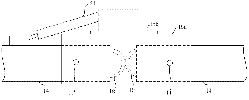
The invention discloses an H-shaped power chassis with ground clearance adjusting function. The H-shaped power chassis comprises a chassis and an engine, a clutch, a gearbox, a differential, transfer cases, chain wheel transmission mechanisms and wheels arranged on the chassis. The engine transfers power to the differential through the gearbox, and the power is respectively transferred to the chain wheel transmission mechanisms of two sides by a left output shaft and a right output shaft of the differential through the transfer cases at two sides of the chassis, so that the power is transferred to the wheels connected with the chain wheel transmission mechanisms of the two sides. The H-shaped power chassis has the advantages that: the transmission ratios of the front and rear wheels of the same side are the same; and when only one of the wheels of the same side slips and the other wheel does not slip, the torque can be transferred to the non-slip wheel, and a driving force is generated by using the adhesive force of the non-slip wheel, so that an automobile smoothly starts or continuously runs, and the passing performance of the vehicle under the rugged pavement condition is improved. Because of adjustable ground clearance, the chassis is suitable for running on the rugged pavement of a mountain land, a hill or the like, and has high passing property and good smoothness and obstacle detouring capacity.

Description

technical field [0001] The invention relates to a power chassis, which belongs to the field of vehicle engineering, in particular to an H-shaped power chassis with the function of adjusting ground clearance. Background technique [0002] Existing automobile chassis usually consists of engine, clutch, gearbox, differential, and wheels. Among them, the power of the transmitter is transmitted to the differential through the clutch, gearbox, and drive shaft, and the differential distributes the power to The left and right half shafts drive the left and right wheels. [0003] Among them, when the differential is installed between the two front wheels of the car and distributes the power to the two front wheels of the car through the left and right axle shafts, it is called front-wheel drive. When the differential is installed between the two rear wheels of the car and distributes the power to the two rear wheels of the car through the left and right axle shafts, it is called rea...

Claims


Application Information

Patent Timeline
Patent Type & Authority Applications(China)
IPC IPC(8): B60G17/0165B60K17/16
Inventor 崔莹徐国艳高巧明王东超范新秀籍俊杰李瑞川高峰
Owner BEIHANG UNIV
Learn More