Blade-free fan

A technology without blades and fans, which is applied to the components of pumping devices for elastic fluids, non-variable pumps, pump devices, etc., which can solve the problems of poor practicability, single function, and difficulty in meeting multiple functions of one machine, etc. problem, to achieve the effect of good signal reception, simple operation and strong practicability

Inactive Publication Date: 2012-02-01
DONGGUAN XUERMEI ELECTRICALTECH
View PDF5 Cites 12 Cited by
  • Summary
  • Abstract
  • Description
  • Claims
  • Application Information

AI Technical Summary

Problems solved by technology

There are many openings on the protective cover of this fan, which is easy to hurt the fingers of children, and there is a certain degree of danger; moreover, this fan uses blades to cut the wind, and when the wind blows to the human body, it will produce a severe wind sensation The impact and the wind are not stable enough, which makes people feel uncomfortable; in addition, the blade fan needs to be disassembled, cleaned, reinstalled and inspected in daily life, which is very inconvenient
[0003] In order to solve the above-mentioned problems, people have designed a kind of concealed blade type electric fan, and this electric fan comprises fuselage, and the front end that communicates with fuselage has the air outlet device of air outlet, and fuselage comprises fuselage shell, is located at fuselage shell The fan blade and the motor inside, the fan blade is driven by the motor to rotate, and the body shell is provided with an air inlet. The fan does not need blades, but the fan can only play the role of promoting air flow. Its single function is difficult to meet the pursuit of modern people. The multi-purpose requirements of one machine, the practicality is not strong
In addition, the control button of the electric fan in the prior art is generally arranged on the body shell, and the control button rotates with the rotation of the body shell during use, which is not conducive to adjusting the number of air outlets of the fan and turning the fan on or off. , inconvenient to use

Method used


Image

  • Blade-free fan
  • Blade-free fan
  • Blade-free fan

Examples


Embodiment 1

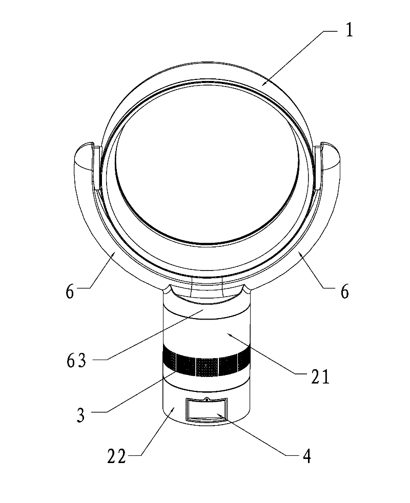
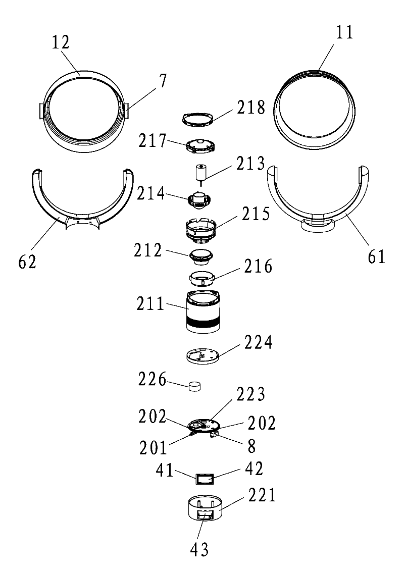
[0058] Such as Figure 1-5 As shown, the bladeless fan of the present invention includes a base 2 for generating airflow and an air outlet device 1 with an air outlet at the front end for ejecting airflow, and the base 2 includes a rotating part for generating airflow 21, and a fixed part 22 arranged at the bottom of the rotating part 21 to drive the rotating part 21 to rotate horizontally. The turbine 212 and the motor 213 in 211, the turbine 212 is driven to rotate by the motor 213, the side wall of the rotating housing 211 is provided with an air inlet 3, and the fixed part 22 includes a fixed housing 221, which is arranged on the The synchronous driving mechanism 222 on the top of the fixed housing 221 drives the rotating housing 211 to rotate horizontally, and the fixed housing 221 is provided with a touch screen control device 4 .

[0059] The touch screen control device 4 of this embodiment is arranged on the fixed part 22. When in use, the synchronous drive mechanism ...

Embodiment 2

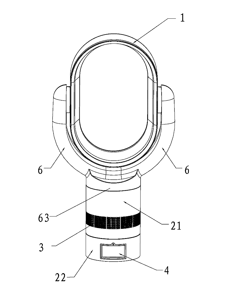
[0070] Such as Figure 6 to Figure 10 As shown, the difference between this embodiment and Embodiment 1 is that an atomizing device 5 is provided at the bottom of the fixing part 22 of this embodiment, and the atomizing device 5 is detachably connected with the fixing part 22, so The atomizing device 5 includes a water tank body, an ultrasonic atomizer 52 connected to the water tank body and a blower mechanism 53, a spray mechanism arranged above the ultrasonic atomizer 52, and a second PCB board 55 connected with the ultrasonic atomizer 52, The spray mechanism is arranged at the rear end of the air outlet device 1 , and the second PCB board 55 is electrically connected with the touch screen control device 4 .

[0071] Under the action of the ultrasonic atomizer 52, the inherent ultrasonic oscillation characteristics of piezoelectric ceramics are used to resonate with the inherent oscillation frequency of piezoelectric ceramics through a certain oscillation circuit, so that th...

Embodiment 3

[0082] Such as Figure 1 to Figure 3 As shown, the difference between this embodiment and Embodiment 2 is that an air inlet channel support 6 is provided between the rotating part 21 of this embodiment and the air outlet device 1, and the air outlet device 1 and the air inlet device 1 The air duct support 6 is hinged, and the bottom of the air intake duct support 6 is formed with an air inlet portion 63, which is detachably fitted with the rotating housing 211, and the cross section of the air inlet portion 63 The area is larger than the cross-sectional area of ​​the air inlet channel bracket 6 , and the air outlet device 1 , the air inlet channel bracket 6 and the rotating part 21 form an air flow channel.

[0083] The air inlet part 63 is detachably fitted with the rotating housing 211, and the diameter of the air inlet part 63 is the same as that of the rotating housing 211, so as to ensure that the airflow generated in the rotating part 21 can pass through the air inlet pa...


PUM


Abstract

The invention relates to the technical field of fans, in particular to a blade-free fan which comprises a base used for generating airflow and an air outlet device used for spraying the airflow and provided with an air outlet at the front end, wherein the base comprises a rotating part used for generating an airflow and a fixing part arranged at the bottom of the rotating part and used for driving the rotating part to horizontally rotate; the rotating part comprises a rotating housing connected with an air outlet device as well as a worm wheel and a motor which are arranged in the rotating housing, wherein the worm wheel is driven by the motor to rotate, the side wall of the rotating housing is provided with an air inlet; the fixing part comprises a fixing housing and a synchronous driving mechanism arranged at the top of the fixing housing and used for driving the rotating housing to horizontally rotate; and the fixing housing is provided with a touch screen control device. The touch screen control device is arranged at the fixing part without rotating due to the change of an air blowing angle, thus the blade-free fan is convenient for the operation of a user, ensures a good signal receiving effect of the touch screen control device, and has the advantages of simpleness in operation, convenience for use and strong practicability.

Description

technical field [0001] The invention relates to the technical field of fans, in particular to a bladeless fan. Background technique [0002] A traditional fan is composed of a fan frame, a driving motor installed in the fan frame, and fan blades rotatably connected to the driving motor. For the safety of the fan, a protective cover is usually installed on the air outlet of the fan. There are many openings on the protective cover of this fan, which is easy to hurt the fingers of children, and there is a certain degree of danger; moreover, this fan uses blades to cut the wind, and when the wind blows to the human body, it will produce a severe wind sensation The impact and the wind are not stable enough, which makes people feel uncomfortable; in addition, the blade fan needs to be disassembled, cleaned, reinstalled and inspected in daily life, which is very inconvenient. [0003] In order to solve the above-mentioned problems, people have designed a kind of concealed blade ty...

Claims


Application Information

Patent Timeline
Patent Type & Authority Applications(China)
IPC IPC(8): F04F5/16F04F5/44
CPCF04D25/10F04F5/16F04F5/44F04D25/08F04D29/002F04D29/705F04D29/40
Inventor 邹小敏
Owner DONGGUAN XUERMEI ELECTRICALTECH
Why Eureka
Try Eureka