Bus transmission device and method

A technology of bus transmission and local bus, which is applied in the field of bus transmission devices and bus transmission, and can solve the problems of low efficiency, different, uncontrolled C hosts, etc.

Inactive Publication Date: 2014-06-11
NEW H3C TECH CO LTD
View PDF3 Cites 0 Cited by
  • Summary
  • Abstract
  • Description
  • Claims
  • Application Information

AI Technical Summary

Problems solved by technology

[0009] In order to overcome the shortcoming of low writing efficiency caused by single-byte writing, most existing I 2 All C devices support page mode writing, but due to different manufacturers' I 2 The physical page sizes supported by C devices are not necessarily the same, such as 8 bytes, 16 bytes, 32 bytes, etc., resulting in I 2 It is difficult to unify the software used for page mode writing in the C host
[0010] 3. I 2 The C host is not very efficient:
[0011] For the case of continuous transmission, if the query mode is used to drive data transmission, it needs to occupy I 2 The resources of the C host are frequently queried, which will reduce the I 2 The efficiency of the C host; and if the interrupt mode is used to drive data transmission, although I 2 The efficiency of the C host can be slightly improved compared with the query method, but for the case of byte transfer or small page transfer, the frequency of interrupts will be relatively high, which will still cause I 2 Too many resources of the C host are occupied, which will also reduce the I 2 C host efficiency;
[0012] Moreover, a predetermined switching interval is required between the read and write operations in the standard mode and the fast mode, and there is also a predetermined page interval between the page and the page when the page mode is written, and the I 2 The above intervals required by C equipment may be different from each other and are not controlled by I 2 C host, thus making the I 2 The C host has to wait for a long time, which will also reduce the I 2 Efficiency of the C host

Method used


Image

  • Bus transmission device and method
  • Bus transmission device and method
  • Bus transmission device and method

Examples


Embodiment Construction

[0053] In order to make the object, technical solution and advantages of the present invention clearer, the present invention will be further described in detail below with reference to the accompanying drawings and examples.

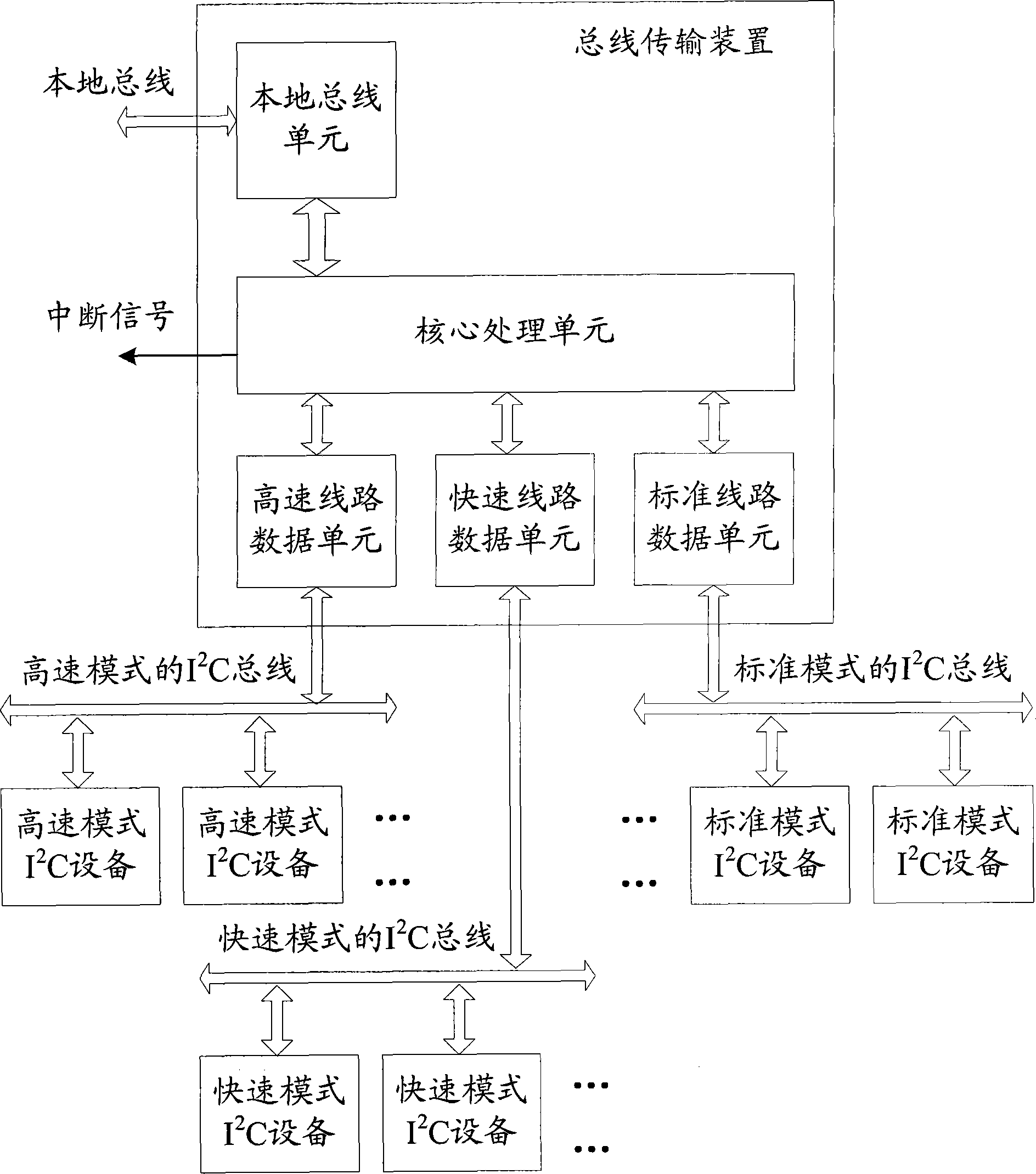
[0054] figure 2 It is a schematic structural diagram of an exemplary bus transmission device in an embodiment of the present invention. Such as figure 2 As shown, the bus transmission device in this embodiment includes: a local bus unit, several line data units respectively corresponding to different speed modes, and a core processing unit.

[0055] The serial or parallel transmission rate of the local bus unit through such as PCI bus is not lower than I 2 Local bus connection for the C bus I 2 C host.

[0056] One line data unit corresponding to each rate mode passes through one I 2 C bus with the I 2 C devices are connected, that is, the high-speed line data unit corresponding to the high-speed mode passes through one I 2 C bus with the I 2 ...


PUM


Abstract

The invention discloses a bus transmission device and method and respectively provides a path of I2C (Inter-Integrated Circuit) bus and I2C equipment for attaching by adopting the speed mode for each speed mode. When the I2C equipment is initialized, the speed mode and the typical speed of each I2C equipment configured by an I2C host are received, so that a corresponding speed mode is adopted for the I2C equipment attached by each path of I2C bus, different typical speeds can be adopted for the I2C equipment adopting the same speed mode and further the mixed speed transmission can be realized. In addition, according to the bus transmission device and method disclosed by the invention, the read-write data can be integrated into logic pages with the same size without paying attention to the size of a physical page, so that byte reading and writing and page reading and writing of physical pages with different sizes can be simultaneously compatible. Furthermore, the efficiency of the I2C host can be improved by reducing report frequencies for interruption.

Description

technical field [0001] The present invention relates to the transmission technology of the serial data bus, relate in particular to be applicable to the internal integrated circuit (Inter-Integrated Circuit, I 2 C) A bus transmission device of the bus, and a bus transmission method. Background technique [0002] I 2 The C bus is a serial bus commonly used for data transmission and is widely used in various fields. [0003] figure 1 I in the prior art 2 An example schematic diagram of a typical application of the C bus. Such as figure 1 As shown, I 2 The C bus includes a serial data signal line (Serial Data, SDA) and a serial clock signal line (Serial Clock Line, SCL), and the CPU in the network communication device acts as an I 2 C host, which passes through the I 2 The C bus is connected with a temperature sensor, a non-volatile erasable read-only memory (E 2 PROM), fans, analog switches, etc. have I 2 C bus interface I 2 C equipment. [0004] However, something...

Claims


Application Information

Patent Timeline
Patent Type & Authority Patents(China)
IPC IPC(8): G06F13/38
Inventor 郭道荣
Owner NEW H3C TECH CO LTD
Why Eureka
Try Eureka