FPGA (Field Programmable Gate Array)-based micro-space oversampling direct-current balance serial deserializer

A DC balancing, micro-space technology, applied in parallel/serial conversion, logic circuits using basic logic circuit components, automatic power control, etc., can solve the problems of high cost of FPGA and no built-in serializer, Achieve the effect of simple implementation, low power consumption and simple structure

Inactive Publication Date: 2012-02-01
SHANGHAI UNIV
View PDF6 Cites 27 Cited by
  • Summary
  • Abstract
  • Description
  • Claims
  • Application Information

AI Technical Summary

Problems solved by technology

[0006] The purpose of the present invention is: in order to solve the problem of high cost of built-in SerDes series FPGA, most FPGA products do not have a built-in SerDes problem, a kind of micro-space oversampling DC balanced serial device based on FPGA is proposed. deserializer, and features low power

Method used


Image

  • FPGA (Field Programmable Gate Array)-based micro-space oversampling direct-current balance serial deserializer
  • FPGA (Field Programmable Gate Array)-based micro-space oversampling direct-current balance serial deserializer
  • FPGA (Field Programmable Gate Array)-based micro-space oversampling direct-current balance serial deserializer

Examples


Embodiment 1

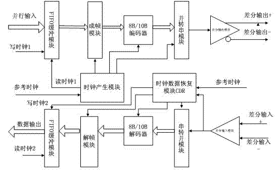
[0027] like figure 1 As shown, this FPGA-based micro space oversampling DC balanced serial deserializer includes a clock data recovery module CDR (1), an 8B / 10B encoder (2), an 8B / 10B decoder (3), the 1. The second two asynchronous FIFO buffer modules (4, 4'), one parallel-to-serial module (5), one serial-to-parallel module (6), one differential signal output module (7), and one differential signal input module (8), a framing module (9), a deframing module (10) and a clock generation module (11). Its characteristics are: at the sending end, after the input data is buffered by the first asynchronous FIFO buffer module (4), it is input to the framing module (9), and then input to the 8B / 10B encoder (2) for encoding, and then passed through parallel transfer The serial module (5) outputs serially, and finally outputs as a differential signal through the sending end of the differential signal output module (7); at the receiving end, the differential signal passes through the diff...

Embodiment 2

[0029] This embodiment is basically the same as Embodiment 1, and the special features are as follows:

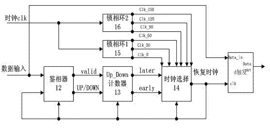
[0030] , clock data recovery module CDR

[0031] like figure 2 : The input data and the recovered clock with the same frequency and different phases enter the phase detector for comparison, and generate an advance / lag signal (up / down), which generates an advance / lag (early / later) signal for clock selection after passing through the lead-lag counter The module controls the switching between 6 clocks with the same frequency and different phases to ensure that the rising edge of the sampling clock is between valid data, so that correct data can be obtained. These modules all use the recovered clock number as clock input to achieve synchronization.

[0032]The above-mentioned phase detector adopts a lead-lag phase detector. The specific circuit is shown in the figure. Four D flip-flops are used to sample the input signal Din to generate three signals s1, s2, and s3. I...


PUM


Abstract

The invention relates to an FPGA (Field Programmable Gate Array)-based micro-space oversampling direct-current balance serial deserializer, aiming to realize verification and design based on serial deserializer in an FPGA without built-in serial deserializer. The FPGA-based micro-space oversampling direct-current balance serial deserializer mainly comprises a clock data recovery (CDR) module, a 8B/10B encoder, a 8B/10B decoder an asynchronous FIFO (First In First Out) buffer module, a clock generation module, a parallel-to-serial conversion module, a serial-to-parallel conversion module, a framing module and a de-framing module. At a transmitting end, data are buffered by the asynchronous FIFO buffer module, input into the 8B/10B encoder (by 8 bits in one frame) for encoding through the framing module, then processed by the parallel-to-serial conversion module and finally output in a differential manner. At a receiving end, a differential signal is accepted by a differential input module and input into the serial-to-parallel conversion module to be output, the output data are decoded by the 8B/10B decoder, then input into the de-framing module, and finally output by the asynchronous FIFO buffer module in a buffer manner.

Description

technical field [0001] The present invention relates to an FPGA-based miniature spatial oversampling DC balanced serial deserializer, specifically a serial-to-parallel conversion technology, low-swing differential technology, codec technology, clock data recovery technology, serial communication technology SerDes. Background technique [0002] SerDes is a mainstream time-division multiplexing (TDM), point-to-point (P2P) serial communication technology. That is, at the sending end, multiple low-speed parallel signals are converted into high-speed serial signals, passed through the transmission medium (optical cable or copper wire), and finally the high-speed serial signals are re-converted into low-speed parallel signals at the receiving end. This point-to-point serial communication technology makes full use of the channel capacity of the transmission medium, reduces the number of required transmission channels and device pins, and thus greatly reduces communication costs. ...

Claims


Application Information

Patent Timeline
Patent Type & Authority Applications(China)
IPC IPC(8): H03M9/00H03K19/177H03L7/081
Inventor 毕卓王镇徐美华
Owner SHANGHAI UNIV
Why Eureka
Try Eureka