DDMI (digital diagnostic monitoring interface) optical module transmitter circuit and optical power monitoring method for same

A technology of optical module and optical power, which is applied in the field of photoelectric communication, can solve the problems of reduced precision, inability to meet the accuracy requirements of the monitoring circuit at the sending end of the optical module, and unstable voltage, so as to achieve the effect of ensuring reliability, easy implementation, and simple sending circuit

Active Publication Date: 2012-02-01
SOURCE PHOTONICS CHENGDU
View PDF3 Cites 18 Cited by
  • Summary
  • Abstract
  • Description
  • Claims
  • Application Information

AI Technical Summary

Problems solved by technology

However, the voltage collected by the single-chip microcomputer at both ends of the sampling resistor will change with various factors such as temperature, and the voltage at both ends is unstable, so the accuracy of the collection will be reduced, which cannot meet the full temperature range of the optical module sending end monitoring circuit in commercial and industrial files. Guaranteed Accuracy Requirements

Method used


Image

  • DDMI (digital diagnostic monitoring interface) optical module transmitter circuit and optical power monitoring method for same
  • DDMI (digital diagnostic monitoring interface) optical module transmitter circuit and optical power monitoring method for same
  • DDMI (digital diagnostic monitoring interface) optical module transmitter circuit and optical power monitoring method for same

Examples


Embodiment Construction

[0044] The present invention will be further described in detail below in conjunction with test examples and specific embodiments. However, it should not be understood that the scope of the above subject matter of the present invention is limited to the following embodiments, and all technologies realized based on the content of the present invention belong to the scope of the present invention.

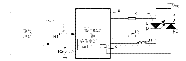
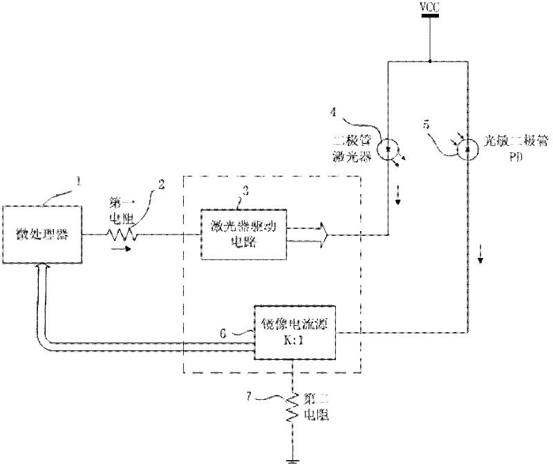
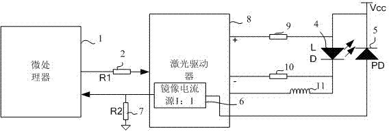
[0045] refer to figure 1 A DDMI optical module sending circuit is shown, the circuit includes a microprocessor 1, a first resistor 2, a laser drive circuit 3, a diode laser 4, a photosensitive diode 5, a mirror current source 6, and a second resistor 7, wherein the microprocessor The device 1 includes a digital-to-analog conversion (D / A) port and an analog-to-digital conversion (A / D) port. The digital-to-analog conversion port of the microprocessor 1 is connected to one end of the first resistor 2, and the other end of the first resistor 2 is connected to the laser drive circuit 3, an...


PUM


Abstract

The invention discloses a DDMI (digital diagnostic monitoring interface) optical module transmitter circuit and an optical power monitoring method for the same. The DDMI optical module transmitter circuit comprises a laser driving circuit, a microprocessor, a laser and a photosensitive diode, wherein the microprocessor drives the laser to emit lasers by the laser driving circuit; the photosensitive diode senses the lasers emitted by the laser, and converts the lasers into an electrical signal; and the microprocessor obtains optical power by the electrical signal of the photosensitive diode. The DDMI optical module transmitter circuit disclosed by the invention realizes monitoring accuracy compensation within an industrial temperature range by an algorithm and a microprocessing system, can be used for ensuring the accuracy of an optical module within a commercial total-temperature range and an industrial total-temperature range, can achieve the monitoring accuracy of + / -1dB and is simple and easy to realize. By the DDMI optical module transmitter circuit and the optical monitoring method for the same, optical power monitoring over the transmitter circuit within a wide range of -6dBm to -10dBm can be met.

Description

technical field [0001] The invention relates to a photoelectric communication technology, in particular to a DDMI optical module sending circuit and an optical power monitoring method thereof. Background technique [0002] An optical module sending end monitoring circuit in the prior art, the monitoring circuit includes a laser component, a laser driver, a sampling resistor and a single-chip microcomputer. When the circuit is working normally, the laser diode installed in the laser component emits light, and the back to the photodiode generates a back current. Since the sampling resistor is connected in series in the current loop, as long as the common-mode voltage at both ends of the sampling resistor is collected by the single-chip microcomputer, the two The magnitude of the back photocurrent can be obtained by dividing the voltage difference at the terminal by the sampling resistor. By writing a coefficient through optical power calibration, a certain optical power can b...

Claims


Application Information

Patent Timeline
Patent Type & Authority Applications(China)
IPC IPC(8): H04B10/08H04B10/158H04B10/071
Inventor 蒋旭帅欣鞠兵杨毅
Owner SOURCE PHOTONICS CHENGDU
Why Eureka
Try Eureka