Thermal protector

A thermal protector, bimetal technology, applied in the protection switch operation/release mechanism, thermal switch, thermal switch components, etc., to achieve the effect of simple structure, excellent current responsiveness or thermal responsiveness

Active Publication Date: 2012-02-01
UCHIYA THERMOSTAT
View PDF5 Cites 2 Cited by
  • Summary
  • Abstract
  • Description
  • Claims
  • Application Information

AI Technical Summary

Problems solved by technology

[0009] However, in the conventional technologies such as Patent Document 1 and Patent Document 2, there is a problem that not only the price of the resistor as an additional component but also the process of assembling the resistor as an additional component is also an additional process. , therefore, it is difficult to avoid the overall price rise of the thermal protector

Method used


Image

  • Thermal protector
  • Thermal protector
  • Thermal protector

Examples


Embodiment 1

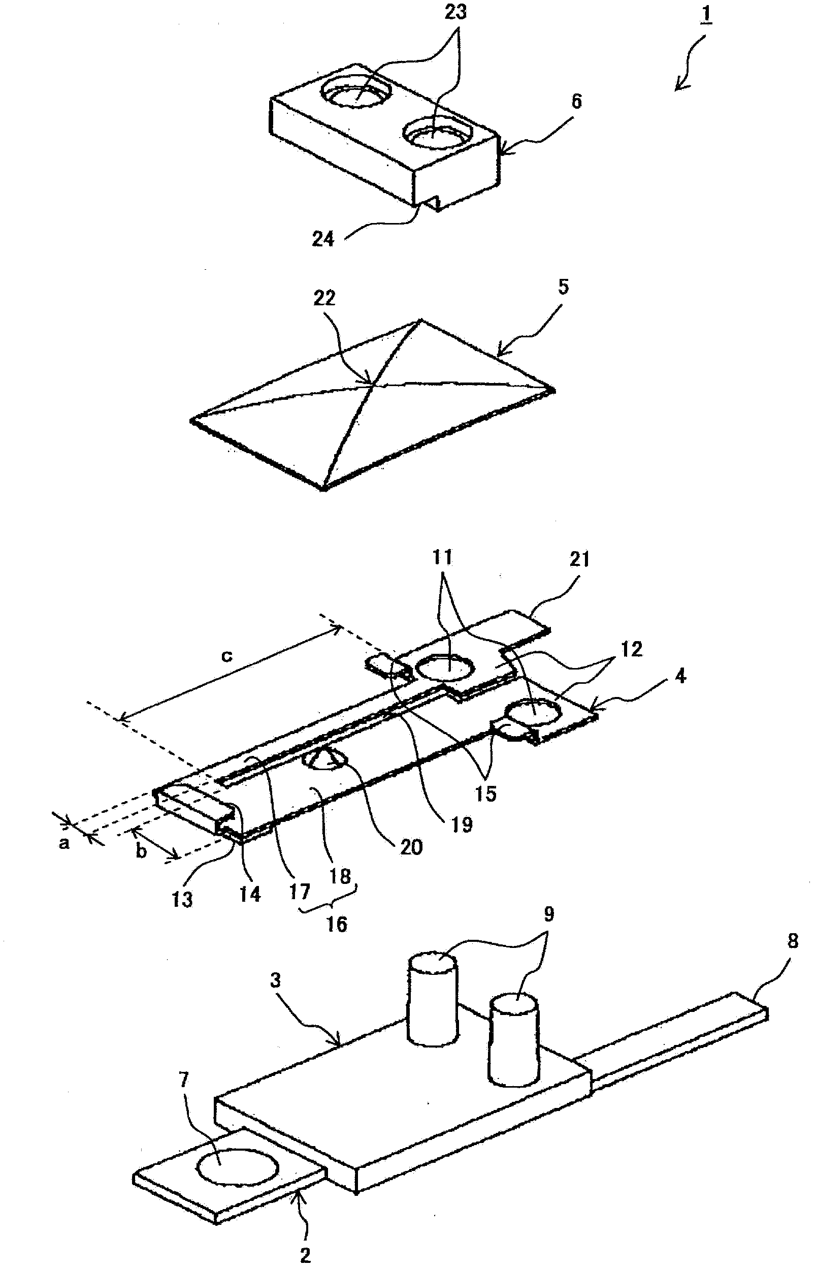
[0027] figure 1 It is an exploded perspective view showing the structure of the thermal protector of Example 1. Such as figure 1 As shown, the thermal protector 1 of this example is composed of a fixed conductor 2 , an insulator 3 , a movable plate 4 , a bimetal 5 and a resin block 6 .

[0028] The fixed conductor 2 has: a fixed contact 7 provided at one end; and a first terminal 8 for external connection connected to the end opposite to the end provided with the fixed contact 7 .

[0029] The insulator 3 is provided between the fixed contact 7 and the first terminal 8 of the fixed conductor 2 by resin molding. This insulator 3 has two pillars 9 integrally molded by resin molding.

[0030] The movable plate 4 has: a fixed portion 12 having a hole 11 fitted to the post 9 on the insulator 3; The opposite position of the fixed contact 7; and a claw 14 and two claws 15, which are used to hold the bimetal 5 on the movable end side where the movable contact 13 is located and the...

Embodiment 2

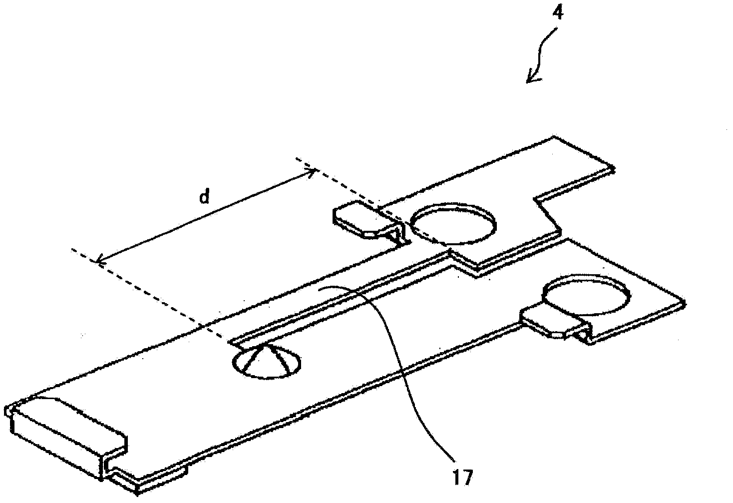
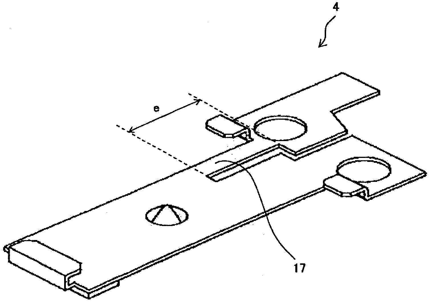
[0063] Image 6 It is a perspective view showing the structure of the movable plate of the thermal protector of Example 2 of this invention. in addition, Image 6 Above the movable plate 4 is also shown the bimetallic strip 5 that moves along with the structure of the movable plate 4 .

[0064] In the movable plate 4 in this example, a protruding portion 29 raised by one step is provided on a portion near the narrow portion 17 at the base of the wide portion 18 side. Like this, when the protruding portion 29 is close to the side of the narrow portion 17, when the fixed-side end of the bimetal 5 engages with the hook 15 on the fixed side of the movable plate 4, the fixed-side end of the bimetal 5 A point 31 of the narrow portion 17 at the center of the portion abuts against the protruding portion 29 .

[0065] As a result, the fixed-side end of the bimetal 5 is inclined toward the wide portion 18 in terms of balance as shown by arrows g and h, with the protruding portion 29 ...

Embodiment 3

[0074] Figure 8 It is an exploded perspective view illustrating the structure of a thermal protector according to Example 3 of the present invention. In addition, in Figure 8 in, with figure 1 The same structure part plus with figure 1 same label. Such as Figure 8 As shown, in the thermal protector 30 of this example, the structure of the fixed conductor 2, the insulator 3 and the resin block 6 is the same as figure 1 The situation is the same.

[0075] The heat protector 30 of this example is deleted figure 1 The movable plate 4, and the bimetallic strip 33 has three ways of the function of the movable plate, the function of the resistor, and the function of the bimetallic strip. That is, the thermal protector 30 of this example is an example of a structure in which a current directly flows through a bimetal strip.

[0076] The bimetallic strip 33 of this example has a fixing portion 35 having a hole 34 fitted to the post 9 in the insulator 3 . In addition, this b...


PUM


Abstract

Disclosed is a simply-structured thermal protector having an excellent current responsivity or thermal responsivity, wherein another process is not necessary to incorporate a resistor. In a press working process wherein a movable plate (4) is cut out from an original material, a movable plate body portion (16) of the movable plate (4) is separated into a small width portion (17) and a large width portion (18) by an elongated hole (19). The movable plate (4) is attached to a stationary conductor (2) via columns (9) of an insulator (3). A bimetal (5) is attached to the movable plate (4), and the assembled components are entirely pressed by a resin block (6). The tips of the columns (9) are melted to secure the securing portions of the assembled components. The large width portion (18) functions as an usual movable plate. The small width portion (17) functions as a conductor in a normal state, and functions as a resistor for excess current.

Description

technical field [0001] The present invention relates to a thermal protector that does not require additional steps in assembling a resistor, has a simple structure, and is excellent in current responsiveness or thermal responsiveness. Background technique [0002] Conventionally, there is known a thermal protector that reversely drives a bimetal by utilizing Joule heat generated by a energized current to open and close a contact. [0003] Most of these thermal protectors use film-like resistors (for example, refer to Patent Document 1), metal wire resistors (for example, Refer to Patent Document 2) and the like to assemble a resistor for generating Joule heat inside as an additional component. [0004] prior art literature [0005] patent documents [0006] Patent Document 1: Japanese Patent No. 3393981 [0007] Patent Document 2: Japanese Patent Laid-Open No. 2003-141977 Contents of the invention [0008] The problem to be solved by the invention [0009] However, i...

Claims


Application Information

Patent Timeline
Patent Type & Authority Applications(China)
IPC IPC(8): H01H37/54H01H37/14H01H37/52
CPCH01H71/16H01H2037/5481H01H37/52H01H37/54
Inventor 武田秀昭
Owner UCHIYA THERMOSTAT
Why Eureka
Try Eureka