Composite punch die for workpiece with multiple long slotted holes

A compound punching die and long slot technology, which is applied in the direction of perforating tools, metal processing, manufacturing tools, etc., can solve the problems that the workpiece waste cannot be discharged from the top to the bottom, punching needles with multiple long slot holes on the aluminum substrate, and low work efficiency. Achieve the effects of increased energy consumption, improved structural strength, and improved work efficiency

Inactive Publication Date: 2012-02-08
兆基荣华模具(深圳)有限公司
View PDF3 Cites 5 Cited by
  • Summary
  • Abstract
  • Description
  • Claims
  • Application Information

AI Technical Summary

Problems solved by technology

In the composite punching die for processing aluminum substrate workpieces with multiple long slots, if the punch pins are installed in the traditional way of knocking the head or hanging on the table, it often leads to the situation that the aluminum substrate has many long slots and the punch pins do not fit tightly.
[0004] In order to improve the strength of this kind of mold, it is necessary to reserve several connecting parts at the corresponding positions of the bar-shaped knife edge of the lower male mold. The setting of this connecting part prevents the workpiece waste falling into the bar-shaped knife edge from being discharged from top to bottom
Adopting the solution of unglue and spring combined with the movement of the upper and lower molds to discharge waste upwards, because the unripe and spring are always in the state of top pressure, the impact and punching tonnage of the punching machine must increase the impact force by 30-50%, which will increase the energy consumption , work efficiency is not high
There is no relevant literature disclosure on the scheme of hydraulically discharging multiple long slot hole workpiece waste materials in the lower mold part.

Method used


Image

  • Composite punch die for workpiece with multiple long slotted holes
  • Composite punch die for workpiece with multiple long slotted holes
  • Composite punch die for workpiece with multiple long slotted holes

Examples


Embodiment Construction

[0025] Further description will be given below in conjunction with the accompanying drawings of the embodiments.

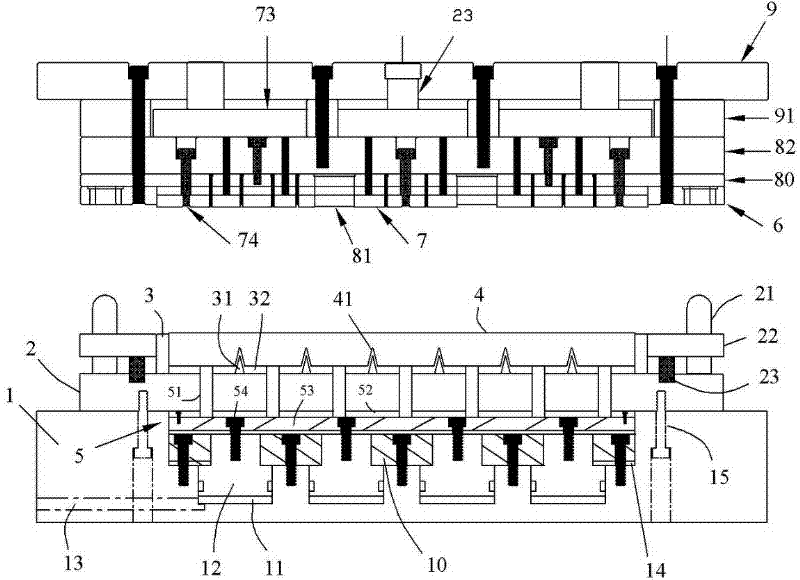
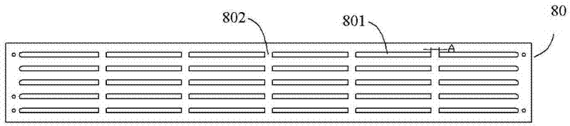
[0026] refer to Figure 1-9 , The multi-slotted workpiece compound punching die includes an upper die part and a lower die part. The main structure of the upper mold part is basically the same as that of the traditional upper mold. The upper mold part mainly includes a die plate 9, a female mold 6 installed on the die plate 9, a punch plate 80 and a needle presser plate 82, and a discharge plate 7 positioned in the die opening of the female mold 6 and the like.

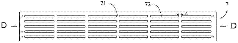
[0027] The discharge plate 7 in the upper mold part is provided with a plurality of strip-shaped via holes 72, and a number of connecting blocks 71 are reserved at the upper opening of each strip-shaped via hole, and the connecting blocks divide the upper opening of the strip-shaped via hole into multiple long mouths; figure 1 The unloading plate 73 and the unloading plate screw 74 etc. are the same as...


PUM

PropertyMeasurementUnit
Heightaaaaaaaaaa
Thicknessaaaaaaaaaa
Heightaaaaaaaaaa

Abstract

The invention discloses a composite punch die for a workpiece with multiple long slotted holes. The composite punch die comprises an upper die and a lower die, wherein a plurality of strip-shaped through holes are formed on a stripper plate of the upper die, and a plurality of connecting blocks are arranged in an upper opening part of each strip-shaped through hole at intervals; and the upper dieis provided with a plurality of strip-shaped punch needles, and each strip-shaped punch needle upwards passes through the corresponding strip-shaped through hole of the stripper plate and is fixed inside a corresponding mounting hole of a punch needle plate. The lower die comprises a lower male die arranged on a lower template, beat needle assemblies, and a base, wherein a plurality of strip-shaped knife edges are arranged on the lower male die, a plurality of connecting parts are reserved on the lower opening part of each strip-shaped knife edge at intervals, and each strip-shaped knife edgeis internally provided with a jacking plate; each beat needle assembly consists of a plurality of rows of beat needles; and the base is internally provided with a plurality of pairs of oil hydraulic cylinder and piston, the beat needle assembly is fixed on each piston, and the lower template is fixed on the base. According to the invention, due to the reserved connecting parts on the strip-shapedknife edges of the lower male die, the composite punch die is increased in structural strength and cannot deform or be fractured easily; and by punching the needles on the punch needle plate by tightly buckling and fixing the punch needles through buckling blocks, so that the problem that the multiple long slotted holes of an aluminum substrate cannot be in close fit with the punch needles is solved; and workpiece wastes are discharged upwards hydraulically, so that the working efficiency is high and the energy consumption is low.

Description

technical field [0001] The invention relates to a punching die for circuit boards, in particular to a compound punching die for punching workpieces with multiple long slots, which is suitable for punching common circuit boards and aluminum base circuit board workpieces with multiple long slots. Background technique [0002] When the compound punching die is used to punch and form ordinary circuit boards, aluminum-based circuit board workpieces, etc., the workpiece waste is mostly discharged downward from the upper and lower fully penetrating knife edges of the lower male die. For the processing of aluminum substrate workpieces with multiple long slot holes, if the lower male mold is still provided with a knife edge that penetrates up and down, the long knife edge will inevitably reduce the strength of the mold, often deform or break, and the mold life will be short. [0003] The punching needle in the traditional composite punching die is installed on the punching needle pla...

Claims


Application Information

Patent Timeline
IPC IPC(8): B21D28/34B21D28/26B26F1/14
Inventor 铙贵振吴永正
Owner 兆基荣华模具(深圳)有限公司
Why Eureka
Try Eureka