

Reusable fabricated end seal structure for immersed tube tunnel
An immersed tube tunnel and prefabricated technology, applied in the field of construction engineering, can solve the problems of increasing project costs and prolonging the construction period, and achieve the effects of saving costs, improving construction efficiency, and good economic benefits
- Summary
- Abstract
- Description
- Claims
- Application Information
AI Technical Summary
Problems solved by technology
Method used
Image

Examples
Embodiment 1
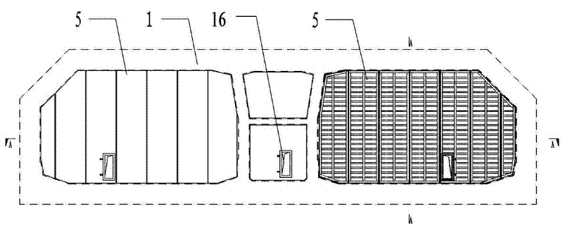
[0033] see Figure 1-5 , in this embodiment, taking a reinforced concrete immersed tunnel as an example, the reusable fabricated end seal structure for the immersed tunnel is described in detail, wherein the cross-sectional layout of the pipe section 1 involved is a porous layout.
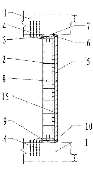
[0034] In this embodiment 1, the end seal structure is the same as the common steel beam / concrete mixed structure end seal door, and it is also necessary to set several vertical supporting beams 2 as the frame structure of the end seal door. Wherein, several main beam corbel embedded parts 4 are pre-embedded on the inner wall near the end surface of the pipe section 1 . The main beam corbel embedded parts 4 are bolted to the main beam corbel 3 to serve as a corbel structure for fixedly supporting the main beam 2 . The inner surfaces of the two ends of the supporting girder 2 and the corbel 3 of the girder are separated by adjustment blocks 14 and bolted by longitudinal adjustment bolts 9 . In the...
Embodiment 2
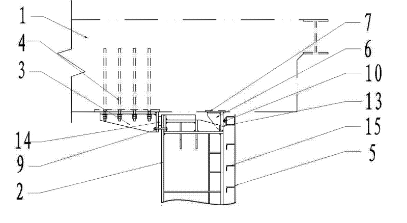
[0044] See attached Figure 6 , The basic arrangement of the end-sealing structure described in this embodiment is roughly the same as that in Embodiment 1. The difference is that the outer supporting side sealing member 6 and the embedded part 7 of the side sealing member are not selected as the supporting structure of the side sealing steel plate 13, but a cement step 12 is integrally cast on the inner wall of the pipe section 1, and the step of the cement step 12 The side sealing steel plate 13 is pre-embedded on the surface. Adopting this structure reduces the welding steps during installation of the side sealing steel plate 13, and further shortens the construction period.
Embodiment 3
[0046] See attached Figure 7 The difference between the end seal structure described in this embodiment and Embodiment 1 is that the supporting main beam 2 is not only arranged at the block joints of the encapsulation door panel 5, but also densely arranged in the middle of the encapsulation door panel 5, that is, except in the encapsulation door panel 5 There is a supporting main beam 2 at the joint of the door panel 5 , and a vertical supporting main beam 2 is provided on the pipe section 1 in the middle relative to the encapsulating door panel 5 . Correspondingly, a spacer rubber strip 11 is added on the inner surface of the package door panel 5 . The spacer rubber strip 11 is arranged in the ring-shaped sealing rubber strip 10, and its two ends are connected with the sealing rubber strip 10 and separated. After the package door panel 5 is installed, the spacer rubber strip 11 is located between the package door panel 5 and the installation facade of the supporting main b...
PUM
 Abstract
Description
Claims
Application Information