Belt wheel unit and belt wheel provided with unit and belt driven structure

A technology of belt transmission and pulleys, which is applied to transmission devices, components with teeth, belts/chains/gears, etc., which can solve problems such as belt heating, inability to achieve continuous speed change, and easy slippage

Inactive Publication Date: 2012-02-08
GREAT WALL MOTOR CO LTD
View PDF6 Cites 7 Cited by
  • Summary
  • Abstract
  • Description
  • Claims
  • Application Information

AI Technical Summary

Problems solved by technology

For example, a multi-speed gearbox has a large volume and needs a control mechanism, and it cannot meet the requirements of continuous speed change.
The existing CVT chain type continuously variable transmission device is composed of a hydraulic system to control the relative movement of the double-sided bevel gear in the coaxial axial direction, thereby changing the radius of rotation of the steel belt matched with the double-sided bevel gear to change the transmission. The speed ratio realizes infinitely variable speed. The process is difficult, high-precision, and high-cost, and it needs to be immersed in oil in the box for transmission. The general speed change mechanism is difficult to bear. In addition, only the edge of the steel belt and the cone are combined during power transmission. The formation of line and surface friction transmission is prone to slipping
When the other kind of trapezoidal belt and conical pulley transmit power, there is a difference between the material of the belt and the pulley, and the belt is inlaid with the two conical pulleys during transmission, which is difficult to separate, resulting in low efficiency, heating of the belt, and difficulty in achieving effective transmission.

Method used


Image

  • Belt wheel unit and belt wheel provided with unit and belt driven structure
  • Belt wheel unit and belt wheel provided with unit and belt driven structure
  • Belt wheel unit and belt wheel provided with unit and belt driven structure

Examples


Embodiment 1

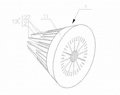
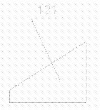
[0022] Depend on figure 1 As shown, the pulley unit 1 of the present invention is set on the pulley shaft 2 during assembly, and has a circular distribution with the axis of the pulley shaft 2 as the center line connected by the connecting part 11 and equidistant from the center line. Meshing teeth 12 with equal tooth thickness, the meshing teeth 12 are arranged at equal intervals, the tooth tops have the same slope relative to the axis of the pulley shaft 2, the minimum distance between the opposite end faces of two adjacent meshing teeth 12 is greater than the tooth thickness, and the pair of connected The purpose of the distance limitation between two meshing teeth 12 is to allow the meshing teeth of another pulley unit to be inserted between adjacent two meshing teeth 12, so as to realize the pulley structure in the second embodiment; the meshing teeth 12 are composed of The connection meshing teeth 121 connected to the pulley rotating shaft 2 by inserting the tooth bottom...

Embodiment 2

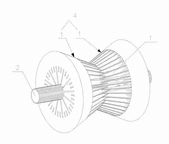
[0025] Depend on image 3 As shown, the pulley 4 of this embodiment is composed of two identical pulley units 1 connected to each other through the meshing teeth 12 of each pulley unit 1 , and each pulley unit 1 has a structure as described in the first embodiment.

Embodiment 3

[0027] Depend on Figure 4-Figure 6 As shown, this embodiment relates to a belt transmission structure, which is composed of two pulley shafts 2 arranged in parallel, a pulley 4 arranged on the pulley shaft 2 and a belt 3 sleeved on the pulley 4, wherein, The pulley 4 has the structure as described in the second embodiment.

[0028] The pulley rotating shaft 2 is provided with an engaging groove 21 parallel to the axis, and the connecting engaging teeth 121 of the pulley 4 are inserted into the engaging groove 21 to realize the axial rotational positioning of the pulley 4 and the pulley rotating shaft 2 .

[0029] The belt 3 has meshing parts 31 arranged at equal intervals. The meshing parts 31 are arranged on the belt body 32 and have an isosceles triangle cross-sectional shape. complementary angles. Driven by the rotation of the pulley rotating shaft 2 , the pulley 4 is inserted into the gaps between the pulley meshing teeth 12 one by one through the engaging portions 31 t...


PUM


Abstract

The invention relates to an element with teeth used for delivering motion, and in particular relates to a belt wheel unit. The belt wheel unit is sleeved on a belt wheel rotor shaft (2), the belt wheel unit is provided with engaging teeth (12) with equal tooth thickness which are connected through a connecting part (11) and take the axial line of the belt wheel rotor shaft (2) as a central line and are in circumferential distribution at equal intervals relative to the central line; the belt wheel unit is characterized in that the engaging teeth (12) are arranged at equal intervals, tooth crests have the same rake ratio relative to the axial line of the belt wheel rotor shaft (2), and the minimum distance between the opposite end faces of the two adjacent engaging teeth (12) is greater than the tooth thickness; and the engaging tooth (12) is composed of a connecting engaging tooth (121) connected with the belt wheel rotor shaft(2) through a tooth bottom and a drive engaging tooth (122) which does not contact the belt wheel rotor shaft(2) at equal intervals. The belt wheel unit adopting the technical scheme provided by the invention has simple structure, thereby realizing the stepless adjustment of the radius of the belt wheel.

Description

technical field [0001] The invention relates to a toothed element for transmitting motion, in particular to a pulley unit, and at the same time, the invention also relates to a pulley and belt transmission structure with the unit. Background technique [0002] Traditional variable speed transmission mechanisms include gear transmission, chain transmission, belt transmission, etc. During the speed change process, the radius of the driving wheel and driven wheel cannot be changed, so the speed ratio of the transmission is fixed. In some specific occasions, in order to meet the different requirements of torque and speed ratio, multiple sets of speed ratio transmission are required to meet the requirements. For example, the multi-speed gearbox has a large volume and needs a control mechanism, and it cannot realize the requirement of continuous speed change. The existing CVT chain type continuously variable transmission device is composed of a hydraulic system to control the rel...

Claims


Application Information

Patent Timeline
Patent Type & Authority Applications(China)
IPC IPC(8): F16H55/46F16H9/16
Inventor 颜广博翁浩宇魏文彬周庆佳
Owner GREAT WALL MOTOR CO LTD
Why Eureka
Try Eureka