
Tunnel lining crack width measuring method and device

A technology of crack width and measurement method, which is applied in measurement devices, optical devices, image data processing, etc., can solve the problems of cumbersome hand-held contact acquisition process, random shooting distance, and complicated image preprocessing.

Inactive Publication Date: 2012-02-08
TONGJI UNIV
View PDF4 Cites 56 Cited by
  • Summary
  • Abstract
  • Description
  • Claims
  • Application Information

AI Technical Summary

Problems solved by technology

In the tunnel, for images of high-level cracks that cannot be touched, the process of hand-held contact acquisition is cumbersome
However, images taken at long distances are sensitive to noise and light, which seriously affects image quality and makes subsequent image preprocessing difficult and complicated.
The area ratio of cracks in long-distance images is much smaller than that in contact images, leaving a large area of ​​complex and changeable background images, coupled with the defects of some edge detection methods, making close-up The edge extraction method for medium and wide cracks is not applicable, and a suitable new method needs to be found
In addition, unlike the contact measurement with a fixed distance, the randomness of the location where the crack occurs leads to the randomness of the shooting distance. It is necessary to find a new calibration method to replace the traditional fixed-distance calibration

Method used


Image

  • Tunnel lining crack width measuring method and device
  • Tunnel lining crack width measuring method and device
  • Tunnel lining crack width measuring method and device

Examples


Embodiment

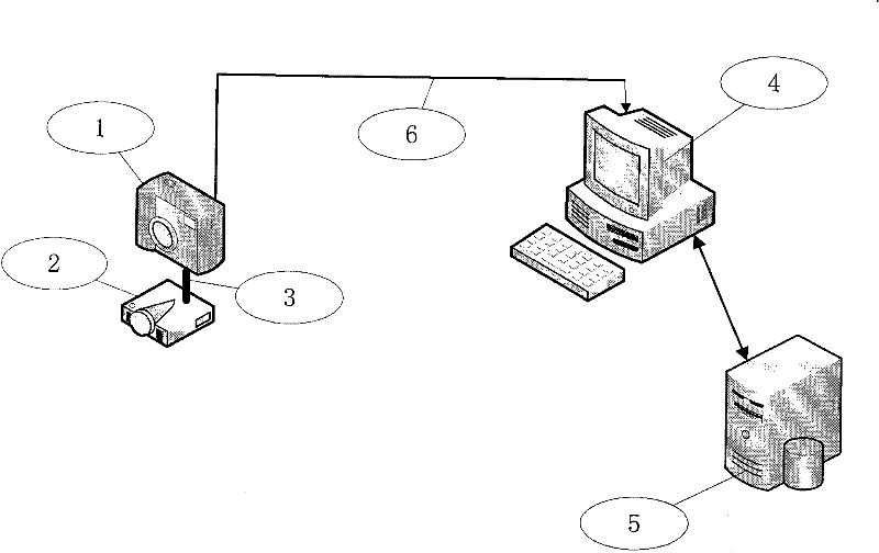
[0070] Such as figure 1 As shown, a method for measuring the crack width of a tunnel lining includes the following steps:

[0071] Step 101, collecting images of cracks by a digital camera, and measuring the collection distance by a laser rangefinder;

[0072] Step 102, select an area to be measured on the collected image, and convert the selected area image into a grayscale image;

[0073] Step 103, determining the threshold value of the grayscale image selected in step 102, and performing binarized image segmentation to obtain the target area;

[0074] Step 104, extracting a white area containing only cracks in the target area;

[0075] Step 105, using the sub-pixel method to extract the edge of the crack to obtain a sub-pixel level edge map;

[0076] Step 106, using the minimum distance method to calculate the pixel width of the crack;

[0077] Step 107, calculate the actual width of the crack according to the calibration ratio of the predetermined pixel actual size and...


PUM


Abstract

The invention relates to a tunnel lining crack width measuring method, which comprises the follow steps of: (1) picking up crack images through a digital camera and measuring pickup distance through a laser distance measuring instrument; (2) selecting a region required to be measured on the picked images and converting selected region images into gray level images; (3) determining the threshold value of the gray level images selected in the second step, cutting binary image cutting, and obtaining a target region; (4) extracting a white region only comprising crack in the target region; (5) extracting the edge of the crack by a sub pixel method, and obtaining sub pixel level edge images; (6) circulating the pixel width of the crack by a minimum distance method; (7) circulating the actual width of the obtained crack according to the calibration proportion of the predetermined actual pixel size and the image pickup distance; and (8) storing the obtained actual width data into a crack data base. Compared with the prior art, the tunnel lining crack width measuring method has the advantages of low cost, high speed, convenience, high precision and the like.

Description

technical field [0001] The invention relates to a tunnel lining crack measurement technology, in particular to a method and device for measuring the width of a tunnel lining crack. Background technique [0002] Quantification of defects such as cracks has always been the goal of non-destructive testing. With the advancement of detection technology, the traditional method of measuring the crack width by human eyes or using a simple instrument such as a reading magnifying glass to estimate, due to the high subjectivity of its personnel, and low accuracy and efficiency, will Gradually replaced by new methods. With the rapid development of computer technology and the continuous improvement of related theories, digital image processing technology has been widely valued in many application fields and has achieved significant pioneering achievements. The photogrammetry technology based on digital image processing has penetrated into the fields of civil engineering such as crack w...

Claims


Application Information

Patent Timeline
IPC IPC(8): G01B11/02G06T7/00G06T5/00
Inventor 朱合华刘学增叶康罗仁立
Owner TONGJI UNIV
Learn More