
Light-emitting diode assembly

A technology of light-emitting diodes and components, applied in the direction of electrical components, semiconductor devices, circuits, etc., can solve the problems of reducing light output efficiency, achieve the effects of improving luminous efficiency, reducing the incidence angle, and reducing the probability of total reflection

Inactive Publication Date: 2012-02-08
佛山市奇明光电有限公司 +1
View PDF4 Cites 0 Cited by
  • Summary
  • Abstract
  • Description
  • Claims
  • Application Information

AI Technical Summary

Problems solved by technology

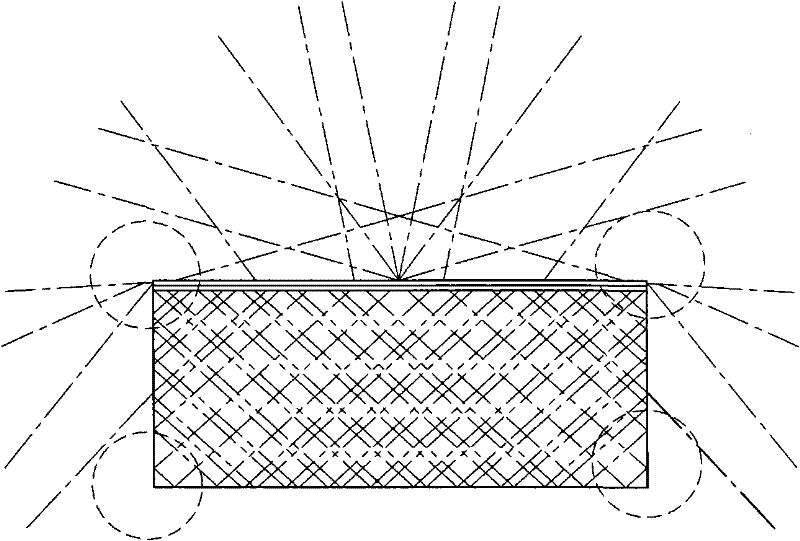
[0004] figure 2 is a schematic diagram of light emitting simulation of light-emitting diode assembly 1, composed of figure 2 It can be seen that since the probability of total reflection of light at the bottom edge of the substrate 11 and the edge of the epitaxial layer (the dotted line range) is very high, few light rays are emitted from here, greatly reducing the light extraction efficiency

Method used


Image

  • Light-emitting diode assembly
  • Light-emitting diode assembly
  • Light-emitting diode assembly

Examples


Embodiment Construction

[0035] A light emitting diode assembly according to a preferred embodiment of the present invention will be described below with reference to related drawings, wherein the same components will be described with the same component symbols.

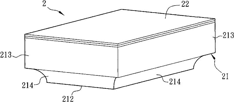
[0036] image 3 It is a three-dimensional schematic diagram of a light emitting diode assembly 2 in a preferred embodiment of the present invention, Figure 4 is a schematic side view of the light emitting diode assembly 2 . Please refer to image 3 and Figure 4 As shown, a light emitting diode assembly 2 according to a preferred embodiment of the present invention includes a substrate 21 and an epitaxial layer 22 . The epitaxial layer 22 is provided on the substrate 21 .

[0037] The material of the substrate 21 may include, for example, sapphire, silicon carbide (SiC), gallium phosphide (GaP) or silicon (Si). Here, sapphire is taken as an example. The substrate 21 has a first side 211 , a second side 212 and an annular side 213 . T...


PUM


Abstract

The invention discloses a light-emitting diode assembly, which comprises a substrate and an epitaxial layer, wherein the substrate is provided with a first side, a second side and an annular side, wherein the first side and the second side are opposite, and the annular side is respectively adjacent to the first side and the second side. The epitaxial layer is arranged at the first side of the substrate, and the annular side is provided with a concave structure extending to the second side from the annular side. In the light-emitting diode assembly disclosed by the invention, the concave structure extends to the first side and the epitaxial layer from the annular side. By the concave structure, the probability that total reflection is caused because light passes through the light-emitting diode assembly can be reduced, and further, the luminous efficiency is improved.

Description

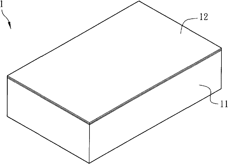
technical field [0001] The invention relates to a light emitting diode assembly. Background technique [0002] A light emitting diode (light emitting diode, LED) is a light-emitting component made of semiconductor materials. Because light-emitting diodes are cold-emitting, they have the advantages of low power consumption, long component life, and fast response speed. In addition, they are small in size and easy to make extremely small or array components. Therefore, with the continuous advancement of technology in recent years, Its application scope covers the indicator lights of computers or home appliances, the backlight of liquid crystal display devices, and even traffic signs or vehicle indicator lights. Improving the light extraction efficiency of light-emitting diodes has been the direction of the industry's efforts. [0003] Please refer to figure 1 As shown, a known light-emitting diode assembly 1 includes a substrate 11 and an epitaxial layer 12. The epitaxial l...

Claims


Application Information

Patent Timeline
Patent Type & Authority Applications(China)
IPC IPC(8): H01L33/20
Inventor 王见仁卢宗宏江宗儒林忠欣
Owner 佛山市奇明光电有限公司
Learn More