Video radar display system

A display system and radar technology, applied in closed-circuit television systems, special data processing applications, instruments, etc., can solve problems such as being susceptible to interference, expensive, dazzling drivers, etc., and achieve the effect of simplifying complexity and improving safety

Inactive Publication Date: 2012-02-08
江彦宏
View PDF6 Cites 7 Cited by
  • Summary
  • Abstract
  • Description
  • Claims
  • Application Information

AI Technical Summary

Problems solved by technology

[0003] However, infrared and ultrasonic radars have a small detection range and a short distance, and are susceptible to interference. When microwave and radio waves need to enhance the detection range, the transmission power must be increased, which is not only harmful to the human body but also expensive
[0004] In addition, t...

Method used


Image

  • Video radar display system
  • Video radar display system
  • Video radar display system

Examples


Embodiment Construction

[0018] The implementation of the present invention will be described in more detail below in conjunction with the accompanying drawings, so that those skilled in the art can implement it after studying this specification.

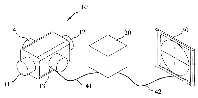
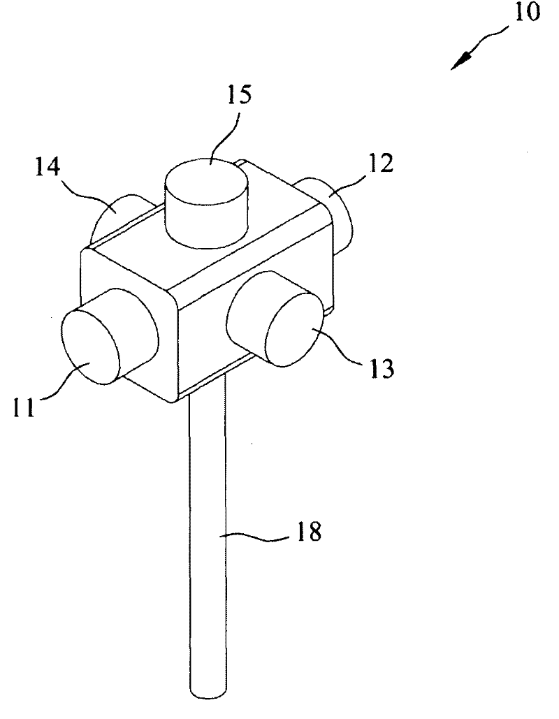
[0019] refer to figure 1 , is a schematic diagram of the video radar display system of the present invention. Such as figure 1 As shown, the video radar display system of the present invention includes a camera array 10, an image processing unit 20, and a display unit 30, wherein the camera array 10 shoots the surrounding environment in different directions to generate multiple environmental images, and the image processing unit 20 uses the first transmission The medium 41 receives the environmental image to perform object recognition processing, object database linking and environmental reconstruction processing to generate environmental image information, and the display unit 30 receives the environmental image information through the second transmission...


PUM


Abstract

The invention discloses a video radar display system, which comprises a camera array, an image processing unit and a display unit, wherein the camera array is provided with a plurality of cameras so as to shoot a plurality of images in different directions; the images of the camera array are received by the image processing unit so as to conduct object identification; the environment is rebuilt through referring to an object data base so as to produce object display information; the object display information is received and a single image picture is displayed by the display unit; the cameras can be twin-lens cameras or tri-lens cameras which are used for producing binary images with distance parallax or images with height parallax; and the images are respectively provided for a computer system to judge the distance or the height of an object. Therefore, the complexity of a displayed picture can be simplified, and the video radar display system is very suitable for providing information for automobile drivers, plane operators or security monitoring units for reference, so as to conveniently judge the surrounding environment.

Description

technical field [0001] The invention relates to a video radar display system, in particular to a video radar display system that displays multiple images in different directions in a single integrated picture. Background technique [0002] How to improve driving safety has always been the direction of the industry's efforts. Among them, many manufacturers have developed the use of infrared, ultrasonic radar, microwave, radio waves to detect obstacles around the vehicle, so as to remind the driver to pay attention to the road conditions, dedicated to the ACC system of the Toyota Camry series of front car collision warning, or dedicated to The side assist system (Side Assist System) of the Audi car series that warns about turning left and right. [0003] However, infrared and ultrasonic radars have small detection ranges and short distances, and are susceptible to interference, while microwave and radio waves need to increase the transmission power when the detection range ne...

Claims


Application Information

Patent Timeline
IPC IPC(8): H04N7/18G06K9/00G06F3/048G06F17/30G06F3/0488
Inventor 江彦宏
Owner 江彦宏
Why Eureka
Try Eureka