Method of desulfurizing molten iron

A processing method and technology for molten iron, applied in furnaces, lighting and heating equipment, stirring devices, etc., can solve the problem of not implementing desulfurization agent addition, and achieve the effects of preventing agglomeration, increasing collision, and improving reaction efficiency

Inactive Publication Date: 2012-02-08
JFE STEEL CORP
View PDF2 Cites 1 Cited by
  • Summary
  • Abstract
  • Description
  • Claims
  • Application Information

AI Technical Summary

Problems solved by technology

In addition, in Patent Document 1, as described above, the treatment of temporarily reducing the rotation speed of the impeller is disclos

Method used


Image

  • Method of desulfurizing molten iron
  • Method of desulfurizing molten iron
  • Method of desulfurizing molten iron

Examples


no. 1 approach

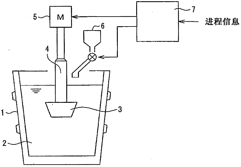
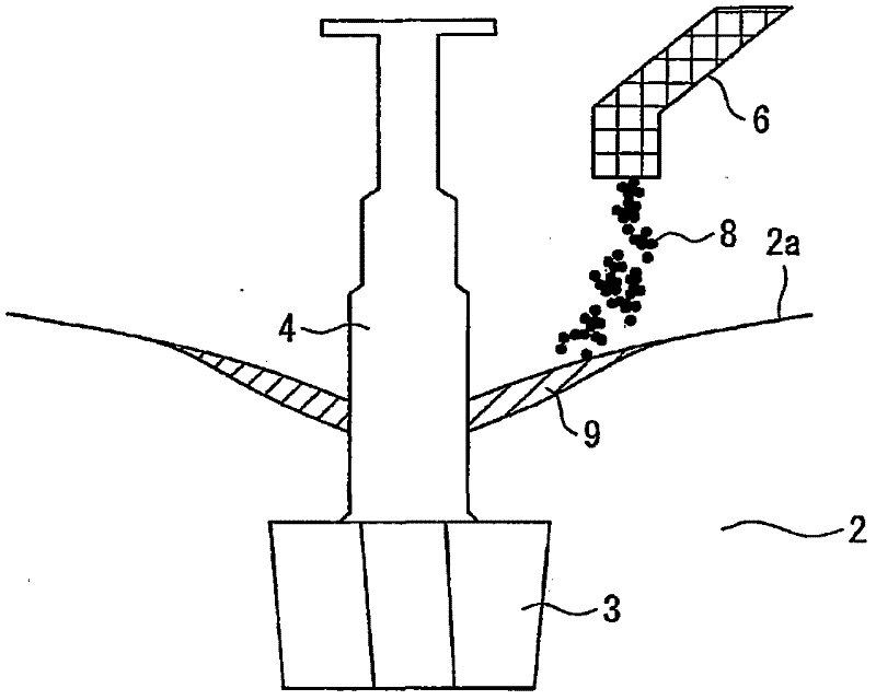
[0025] Next, a first embodiment of the present invention will be described with reference to the drawings. However, the present invention is not limited to the examples disclosed below. figure 1 It is a conceptual diagram showing the desulfurization treatment facility of molten iron in this embodiment. in addition, image 3 Expressed in figure 1 An example of the utilization state of the shown desulfurization treatment facilities.

[0026] (structure)

[0027] First, the device structure will be described. figure 1 Among them, the label 1 is the hot-metal ladle. Molten iron 2 is accommodated in the molten iron tank 1 . By inserting the impeller 3 into the molten iron tank 1 containing the molten iron 2 from above, the impeller 3 is immersed in the molten iron 2 . The impeller 3 is constituted by, for example, an impeller 3 with four blades (four-bladed: four leaves, cross-shaped: cross-shaped). The rotating shaft 4 of the impeller 3 is arranged with its shaft facing...

no. 2 approach

[0052] Next, a second embodiment will be described with reference to the drawings. In addition, the same code|symbol is attached|subjected and demonstrated about the apparatus etc. which are the same as said 1st Embodiment. In addition, similarly, it is not limited to the following examples.

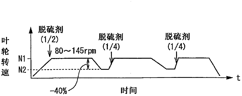
[0053] The basic structure of this embodiment is the same as that of the above-mentioned first embodiment. However, there is a difference in the elevation control of the impeller 3 in the desulfurization process. Not described in the first embodiment, however, figure 1 The desulfurization treatment equipment of the present invention is equipped with an impeller elevating device (not shown) for elevating the impeller 3 . In the general lifting control of the impeller 3, the impeller 3 is lowered into the molten iron tank 1 before the desulfurization treatment to impregnate the impeller 3 into the molten iron 2, and then the height of the impeller 3 is kept constant during the desulfur...

Embodiment

[0068] According to the following conditions, in the first embodiment ( figure 2 ), the second embodiment ( Figure 4 ) and comparative examples (with figure 2 The desulfurization agent is put into the mode, and the impeller speed is fixed in N1) for desulfurization treatment of molten iron. The height of the upper surface of the impeller under normal stirring is 100cm lower than the surface of the static molten iron.

[0069] ·molten iron

[0070] Composition before treatment: C: 4.3% by mass, S: 0.023% by mass (S 0 )

[0071] Capacity: 300 tons

[0072] ·Desulfurizer

[0073] Type: Lime

[0074] Consumption: 1500kg

[0075] · Processing time

[0076] Each treatment at speed N1: about 8 minutes

[0077] Each treatment at speed N2: about 2 minutes

[0078] The results obtained are as follows. S f is the S concentration of molten iron after desulfurization treatment.

[0079] The first embodiment: S removal rate ln(S 0 / S f ) = 2.1

[0080] ·Second embodiment...


PUM


Abstract

A method of desulfurizing molten iron (2) which comprises stirring molten iron (2) to which a desulfurizing agent (8) has been added and thereby dispersing the desulfurizing agent (8) to desulfurize the molten iron (2), wherein the desulfurizing agent (8) is added to the molten iron (2) multiple times in a manner such that stirring is temporarily stopped or conducted at a reduced stirring force at least one time the desulfurizing agent (8) is added subsequent to the first addition in order to cause slag (9) to rise to the surface of the molten iron (2), and the desulfurizing agent (8) is added to the floating slag (9). Preferably, when the slag is caused to rise to the surface, the impeller immersion depth is reduced. Preferably, the impeller is moved downward when the floating slag is taken into the molten iron. The efficiency of reaction of the added desulfurizing agent is thereby improved.

Description

technical field [0001] The present invention relates to a technique for desulfurizing hot metal (pig iron) by adding a desulfurization agent to hot metal (pig iron) and stirring (stir). Background technique [0002] Conventionally, as a method of desulfurizing molten iron by adding a desulfurizing agent to molten iron and stirring with an impeller (rotating blade: impeller), there is, for example, the technique described in Patent Document 1. In Patent Document 1, it is disclosed that the impeller is rotated at a predetermined rotation speed from the start of the desulfurization treatment until a predetermined time elapses (preliminary process), then the rotation speed of the impeller is relatively reduced or stopped (intermediate process), and then the rotation speed of the impeller is relatively increased or restarted. Start spinning (post process) technique. The purpose of this technology is to promote the floating of the desulfurizing agent in the mid-term process ([001...

Claims


Application Information

Patent Timeline
IPC IPC(8): C21C1/02
CPCC21C1/06C21C7/0075C21C7/0645F27D27/00C21C1/02
Inventor 田中芳幸大山智史井上祥规井泽智生
Owner JFE STEEL CORP
Why Eureka
Try Eureka