Lifting valve structure for dirt discharging pipeline

A technology for sewage pipelines and valves, which is applied in the field of lifting valve structures for sewage pipelines, can solve the problems of heavy rainfall, full water operation, valve corrosion, etc., and achieves the effects of simple operation, compact layout and prevention of rupture.

Pending Publication Date: 2020-01-24
WUXI MUNICIPAL DESIGN INST
View PDF0 Cites 0 Cited by
  • Summary
  • Abstract
  • Description
  • Claims
  • Application Information

AI Technical Summary

Problems solved by technology

However, according to time experience, especially in the Jiangnan area, there are many polders, and the rainfall is relatively large during the rainy season, and the rainfall lasts for a long time. It often occurs that the underground rainwater pipe network is full of water. At this time, rainwater is easy to flow back into the valve well. And cause the valve to be immersed in water for a long time
Cause the valve to corrode, or even fail to open and close, which brings great safety hazards to the municipal water supply and drainage pipe network system

Method used


Image

  • Lifting valve structure for dirt discharging pipeline
  • Lifting valve structure for dirt discharging pipeline
  • Lifting valve structure for dirt discharging pipeline

Examples


Embodiment Construction

[0024] Below the present invention will be further described in conjunction with the embodiment in the accompanying drawing:

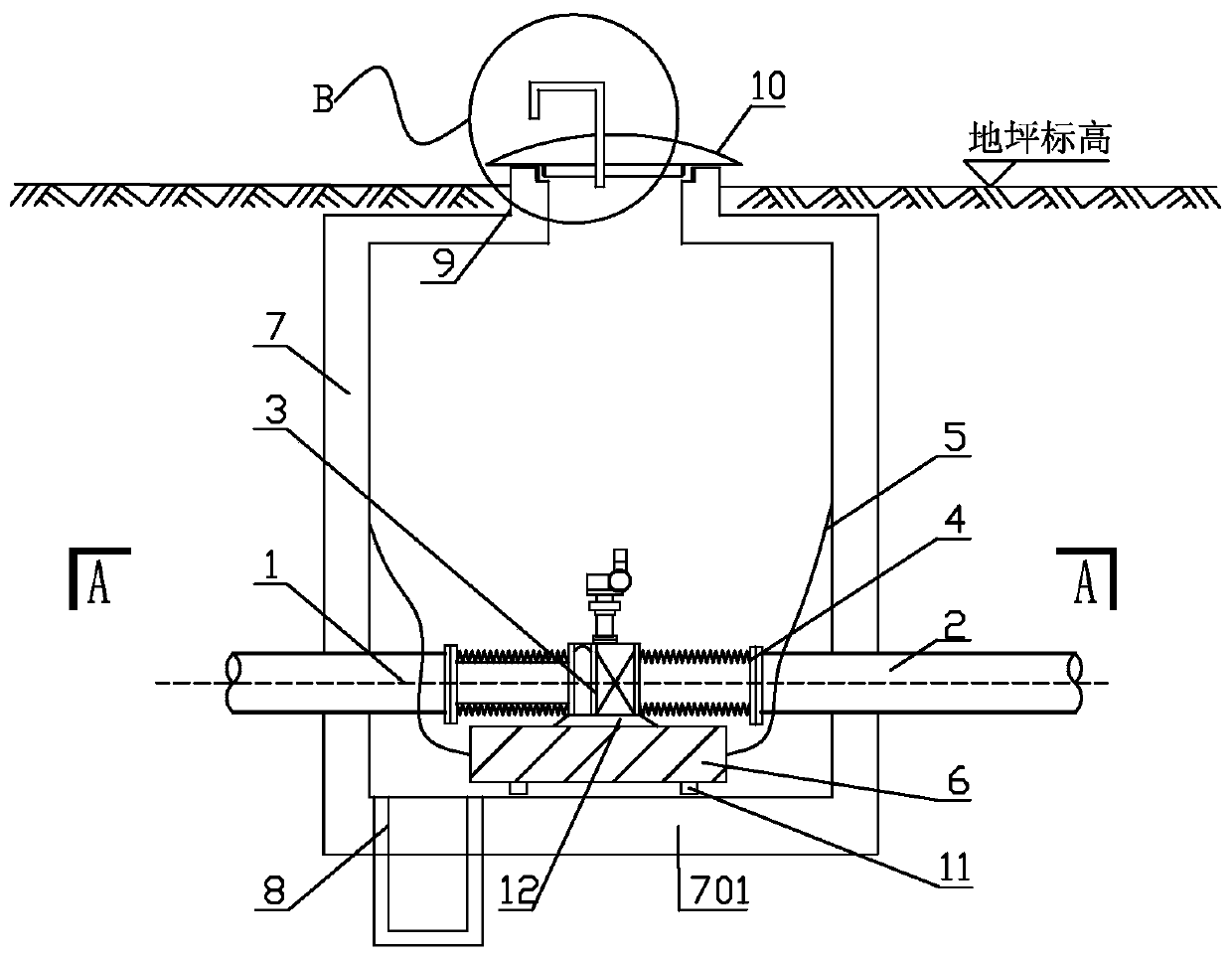
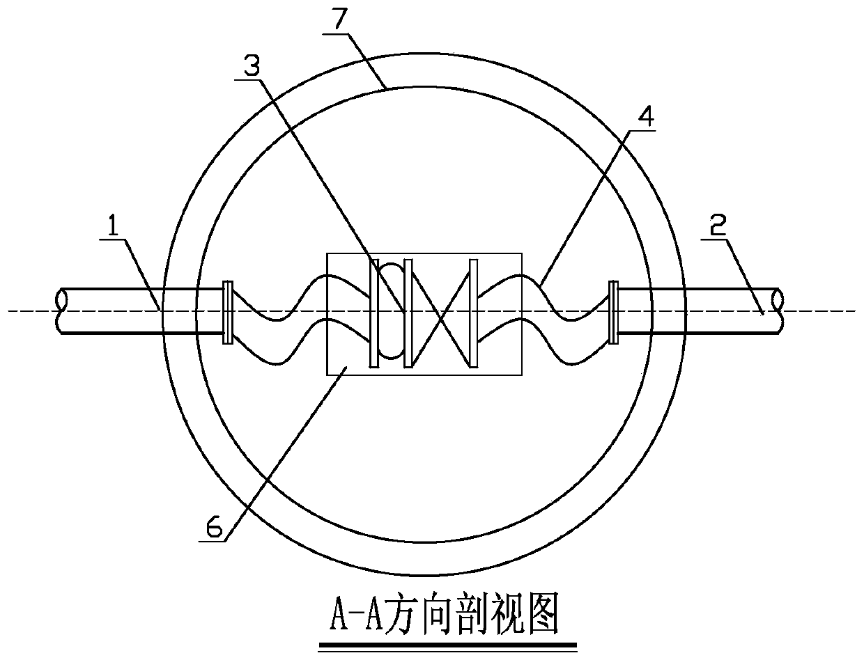
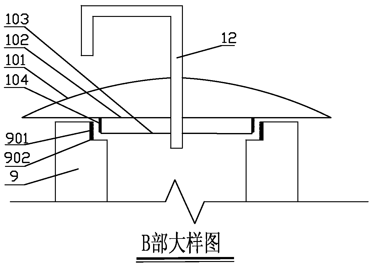
[0025] Such as Figure 1-Figure 3 As shown, it includes upstream pipe 1, downstream pipe 2, valve 3, flexible pipe 4, elastic traction rope 5, floating pad 6, well body 7, bottom plate 701, sump 8, inspection port 9, threaded well cover 10, upper cover 101 , lower cover 102 , swivel plate 103 , leg 11 and air duct 12 .

[0026] The idea, specific structure and technical effects of the present invention will be further described below in conjunction with the accompanying drawings, so as to fully understand the purpose, features and effects of the present invention.

[0027] A lifting valve structure for sewage pipelines according to the present invention includes a well body 7, and round holes are symmetrically opened on the opposite side walls of the lower part of the well body 7, and an upstream pipe 1 and a downstream pipe 2 are respectively install...


PUM


Abstract

The invention relates to a lifting valve structure for a dirt discharging pipeline, and belongs to the technical field of waste water treatment mechanical equipment. The lifting valve structure comprises a well body, an upstream pipe and a downstream pipe are arranged in a well body circular hole, the outlet end of the upstream pipe and the inlet end of the downstream pipe are each connected withone flexible pipe, a valve is connected between the two flexible pipes and fixed to a floating pad, and the floating pad is located on a bottom plate in the well body. Stand bars are arranged at the bottom of the floating pad, and a gap is formed between the bottom face of the floating pad and the upper surface of the bottom plate. A water gathering pit is arranged on one side below the well bodyand connected to a rainwater pipe network through a water discharging pipe. The lifting valve structure is compact in structure arrangement, operation is simple and convenient, a channel can be provided for accumulated water, and the final accumulated water can be thoroughly discharged; and the situation that the tension of the valve, the upstream pipe and the downstream pipe is too high, and consequently the connector strength is influenced can be prevented; and water flow can be effectively guided, the edge stretches out of the caliber of an overhauling port, and road surface rain water pouring can be effectively prevented.

Description

technical field [0001] The invention relates to a lifting valve structure for a sewage pipeline, which belongs to the technical field of sewage treatment machinery and equipment. Background technique [0002] The valve well is the valve installed at the connection between the underground pipeline and the underground pipeline. The purpose of setting the valve well is to facilitate the operation when it is necessary to open and close some pipe network operations or maintenance. As the hub of the pipeline, the valve well has a high degree of sealing requirements. [0003] In the prior art, it is a difficult problem to discharge the stagnant water in the valve well. Usually, a sump is provided at the bottom of the valve well. The sump can be set to be disconnected from the stormwater system or connected to the stormwater system. First, if the sump is not connected to the rainwater system, the rainwater in the valve well can be placed in the preset sump by the worker with a te...

Claims


Application Information

Patent Timeline
Patent Type & Authority Applications(China)
IPC IPC(8): E03F3/04E03F7/00
CPCE03F3/04E03F7/00
Inventor 薛峰蔡丹新段腾腾郑阳光姜云芳王海彦
Owner WUXI MUNICIPAL DESIGN INST
Why Eureka
Try Eureka