Automatic torsion machine with heating device

A technology of heating device and spring winding machine, applied in the direction of wire rod processing, wire manufacturing of springs, and other household appliances, can solve the problems of long processing cycle, improved economic benefits, poor spring consistency and tooling versatility, etc., and achieves a degree of automation. High, reliable transmission balance, improve the effect of wire feeding accuracy

Active Publication Date: 2012-10-10
JIANGSU ZHONGMING XIANGHE SEIKO
View PDF5 Cites 0 Cited by
  • Summary
  • Abstract
  • Description
  • Claims
  • Application Information

AI Technical Summary

Problems solved by technology

[0002] At present, the more common spring coiling machines with heating devices for processing scroll springs in the market mainly include guide conveying mechanism, material cutting mechanism, heating mechanism and The processing steps of the bending mechanism are: straightening → material cutting → heating → bending → manual spring winding. The shortcomings of this kind of spring winding machine with heating device in the actual use process are: first, it needs more than one person Production, production efficiency is low, especially manual winding spring, not only the processing cycle is longer, the processing efficiency is low, the processing cost is high, it is not conducive to the enterprise to improve economic benefits, but also the human factor is large in the processing process, the spring consistency is poor, and the quality It cannot be guaranteed; secondly, different tooling is required to wind springs of different specifications, and the universality of the tooling is poor
[0003] Aiming at the problems of low production efficiency, long processing cycle, high production cost, poor spring consistency and tooling versatility existing in existing spring winding machines, the applicant carried out Active and effective exploration has found a solution to the problem. The technical solution to be introduced below is generated under this background

Method used


Image

  • Automatic torsion machine with heating device
  • Automatic torsion machine with heating device
  • Automatic torsion machine with heating device

Examples


Embodiment Construction

[0017] In order to enable the examiners of the patent office, especially the public, to understand the technical essence and beneficial effects of the present invention more clearly, the applicant will describe in detail below in conjunction with the accompanying drawings in the form of embodiments, but none of the descriptions of the embodiments is a description of the present invention. Restriction of the inventive solution, any equivalent transformation made according to the concept of the present invention which is only in form but not in substance shall be regarded as the scope of the technical solution of the present invention.

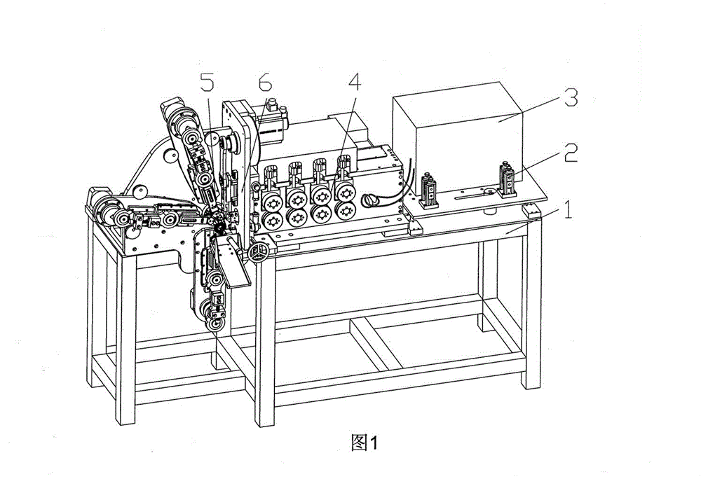
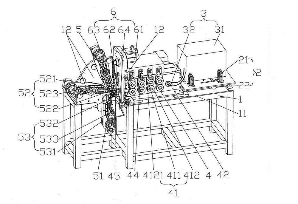
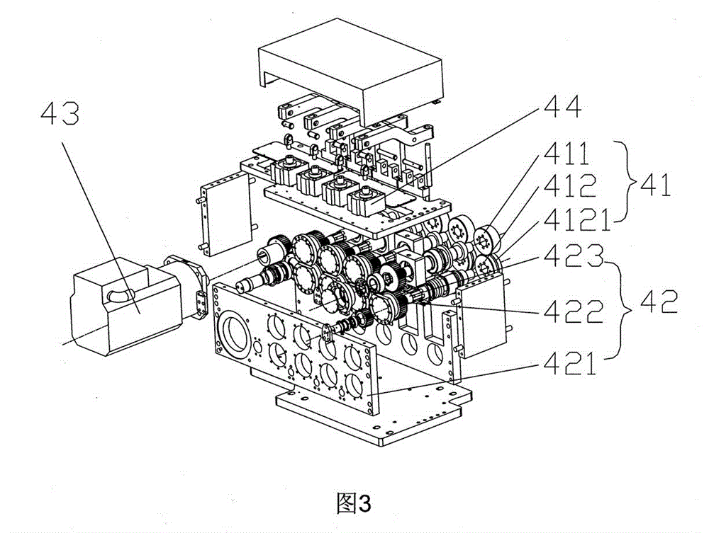
[0018] Please refer to figure 1 , figure 2 and combine image 3 , Figure 4 , Figure 5 , Figure 6 and Figure 7 , the frame 1 of the present invention is provided with a frame platform 11 and a wall plate 12 for installing various mechanisms. The guide conveying mechanism 2 includes a guide wheel assembly 21 and a guide rail ...


PUM


Abstract

The invention discloses an automatic torsion machine with a heating device and belongs to the technical field of spring manufacturing equipment. The automatic torsion machine comprises a stander, a guide conveying mechanism, a heating mechanism, a wire feeding mechanism, a torsion mechanism and a cutting-off mechanism, wherein a stander platform and a wall plate are arranged on the stander; the guide conveying mechanism comprises a guide wheel component and a guide rail; the heating mechanism comprises a high frequency machine and a heating wire; the wire feeding mechanism comprises a wire feeding wheel set, a gear box, a gear driving motor, a compaction cylinder and a wire feeding opening; the torsion mechanism comprises a center driving device, a molding manipulator and a supporting manipulator; and the cutting-off mechanism comprises a cutting-off motor, a cutting-off transmission system, a cutting-off cutter and an output opening. The automatic torsion machine has the advantages that: operation of multiple persons is not required, so labors can be saved; furthermore, the wire feeding precision of spring steel wires can be improved, the automation degree is high, the transmission balance is reliable, and the uniformity is high.

Description

technical field [0001] The invention belongs to the technical field of spring manufacturing equipment, and in particular relates to an automatic spring winding machine with a heating device, which is used for automatically winding scroll springs. Background technique [0002] At present, the more common spring coiling machines with heating devices for processing scroll springs on the market mainly include guiding conveying mechanism, cutting mechanism, heating mechanism and bending mechanism. The processing steps are: straightening → cutting →Heating→Bending→Manual spring winding, this kind of spring winding machine with heating device has the shortcomings in the actual use process: first, it needs multiple people to produce, and the production efficiency is low, especially manual spring winding, not only Long, low processing efficiency, high processing cost, which is not conducive to enterprises to improve economic benefits, and in the processing process, the human factor i...

Claims


Application Information

Patent Timeline
Patent Type & Authority Patents(China)
IPC IPC(8): B21F35/00
Inventor 邹耀忠
Owner JIANGSU ZHONGMING XIANGHE SEIKO
Why Eureka
Try Eureka