Full-automatic charging-discharging mechanism used for LED (Light Emitting Diode) laser cutting

A laser cutting and fully automatic technology, applied in laser welding equipment, welding equipment, metal processing equipment, etc., can solve the problems of low efficiency of LED wafer cutting and unstable manual operation

Inactive Publication Date: 2012-02-15
SUZHOU DELPHI LASER
View PDF7 Cites 25 Cited by
  • Summary
  • Abstract
  • Description
  • Claims
  • Application Information

AI Technical Summary

Problems solved by technology

[0005] The purpose of the present invention is to overcome the deficiencies in the prior art and provide a fully automatic loading and unloading mechani

Method used


Image

  • Full-automatic charging-discharging mechanism used for LED (Light Emitting Diode) laser cutting
  • Full-automatic charging-discharging mechanism used for LED (Light Emitting Diode) laser cutting
  • Full-automatic charging-discharging mechanism used for LED (Light Emitting Diode) laser cutting

Examples


Embodiment Construction

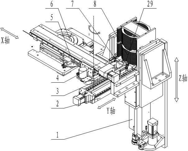
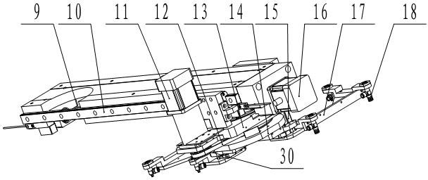
[0020] Such as figure 1 As shown, the fully automatic loading and unloading mechanism applied to LED laser cutting includes mutually independent X-axis transmission unit 4, Y-axis transmission unit 2 and Z-axis transmission unit 1 arranged in X, Y, and Z axes, such as figure 2 As shown, the X-axis transmission unit 4 includes an X-axis ball screw 9, an X-axis linear slide rail 10, an X-axis motor 16, and an X-axis slide plate 13. The X-axis slide plate 13 is placed in the X-axis linear slide rail 10, and the X-axis slide plate 13 and the X-axis ball screw 9 form a screw transmission pair, and the X-axis ball screw 9 is drivingly connected to the X-axis motor 16. The X-axis slide plate 13 is equipped with a rotating shaft 3, and the rotating shaft 3 is driven and connected to the motor through the timing belt 12. The rotating shaft 3 is provided with a first suction cup 5 and a second suction cup 7, the first suction cup 5 and the second suction cup 7 form an angle of 90° in t...


PUM


Abstract

The invention relates to a full-automatic charging-discharging mechanism used for LED (Light Emitting Diode) laser cutting, and the mechanism comprises an X-shaft conveying unit, a Y-shaft conveying unit and a Z-shaft conveying unit, wherein an X-shaft sliding plate of the X-shaft conveying unit is arranged in an X-shaft linear sliding rail; a screw driving pair is composed of the X-shaft sliding plate and an X-shaft ball screw; the X-shaft ball screw is in driving connection with an X-shaft motor; a rotating shaft is mounted on the X-shaft sliding plate; a first sucker and a second sucker are arranged on the rotating shaft; a Y-shaft sliding plate of the Y-shaft conveying unit is arranged in a Y-shaft linear sliding rail; a screw driving pair is composed of the Y-shaft sliding plate and a Y-shaft ball screw; the Y-shaft ball screw is in driving connection with a Y-shaft motor; a clamping mechanism is mounted on the Y-shaft sliding plate; a Z-shaft sliding plate of the Z-shaft conveying unit is arranged in a Z-shaft linear sliding rail; a screw driving pair is composed of the Z-shaft sliding plate and a Z-shaft ball screw; and the Z-shaft ball screw is in driving connection with a Z-shaft motor. The full-automatic charging-discharging mechanism can be applied to the LED laser cutting to realize the full-automatic charging-discharging and solve the problems of low efficiency of traditional LED wafer cutting and instability of manual operation.

Description

technical field [0001] The invention relates to a fully automatic loading and unloading device, in particular to a fully automatic loading and unloading mechanism applied to LED laser cutting. Background technique [0002] LED laser cutting equipment is a special laser equipment used for cutting GaN blue light LED wafers on sapphire substrates. Blue light LED wafers are usually grown on sapphire substrates by vapor phase deposition process GaN crystals, and finally on the wafers Several LED light-emitting units with independent light-emitting functions are formed by screen printing technology and electrodes. [0003] At present, laser cutting technology has been maturely applied to blue LED wafer cutting. In the production process, the blue film or white film is fixed on a steel ring, and then the LED wafer is adhered to the blue film or white film. For better handling of LED wafers, put the steel rings that have been glued to the wafer into the clamp for handling. At prese...

Claims


Application Information

Patent Timeline
IPC IPC(8): B23K26/42B23K26/70
Inventor 赵裕兴胡剑
Owner SUZHOU DELPHI LASER
Why Eureka
Try Eureka