Oil-free double-screw compressor

A compressor and twin-screw technology, used in mechanical equipment, machines/engines, rotary piston machines, etc., can solve the problems of easy deformation, mechanical strength can not meet the mechanical strength, and the processing of the profile structure is difficult. Processing difficulty, the effect of increasing the scope of application

Inactive Publication Date: 2012-02-15
江西隆恒科技有限公司
View PDF6 Cites 7 Cited by
  • Summary
  • Abstract
  • Description
  • Claims
  • Application Information

AI Technical Summary

Problems solved by technology

[0008] First of all, due to the equipment characteristics of the oil-free twin-screw compressor, the machining accuracy of the female rotor and the male rotor is particularly high, and the steel structure is easily deformed during heat treatment processes such as surface quenching, resulting in a gap between the male rotor and the female rotor. The matching profile structure is difficult to process; in addition, in some special fields, the female rotor and the male rotor of the oil-free twin-screw compressor need to be processed with some special materials, and the mechanical strength of this special material cannot meet the needs of the female rotor and male rotor. The mechanical strength of the joints between the male rotor and synchronous gears and bearings
[0009] Therefore, the oil-free twin-screw compressor in the prior art, because of the problem of the female rotor and the male rotor, has caused the application range of the oil-free twin-screw compressor to be greatly limited

Method used


Image

  • Oil-free double-screw compressor
  • Oil-free double-screw compressor
  • Oil-free double-screw compressor

Examples


Embodiment Construction

[0040] The following will clearly and completely describe the technical solutions in the embodiments of the present invention with reference to the accompanying drawings in the embodiments of the present invention. Obviously, the described embodiments are only some, not all, embodiments of the present invention. Based on the embodiments of the present invention, all other embodiments obtained by persons of ordinary skill in the art without making creative efforts belong to the protection scope of the present invention.

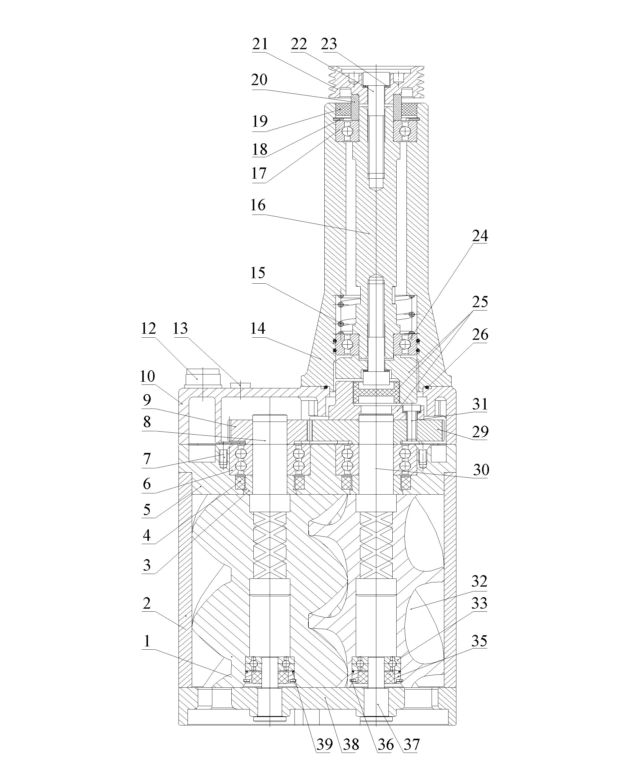
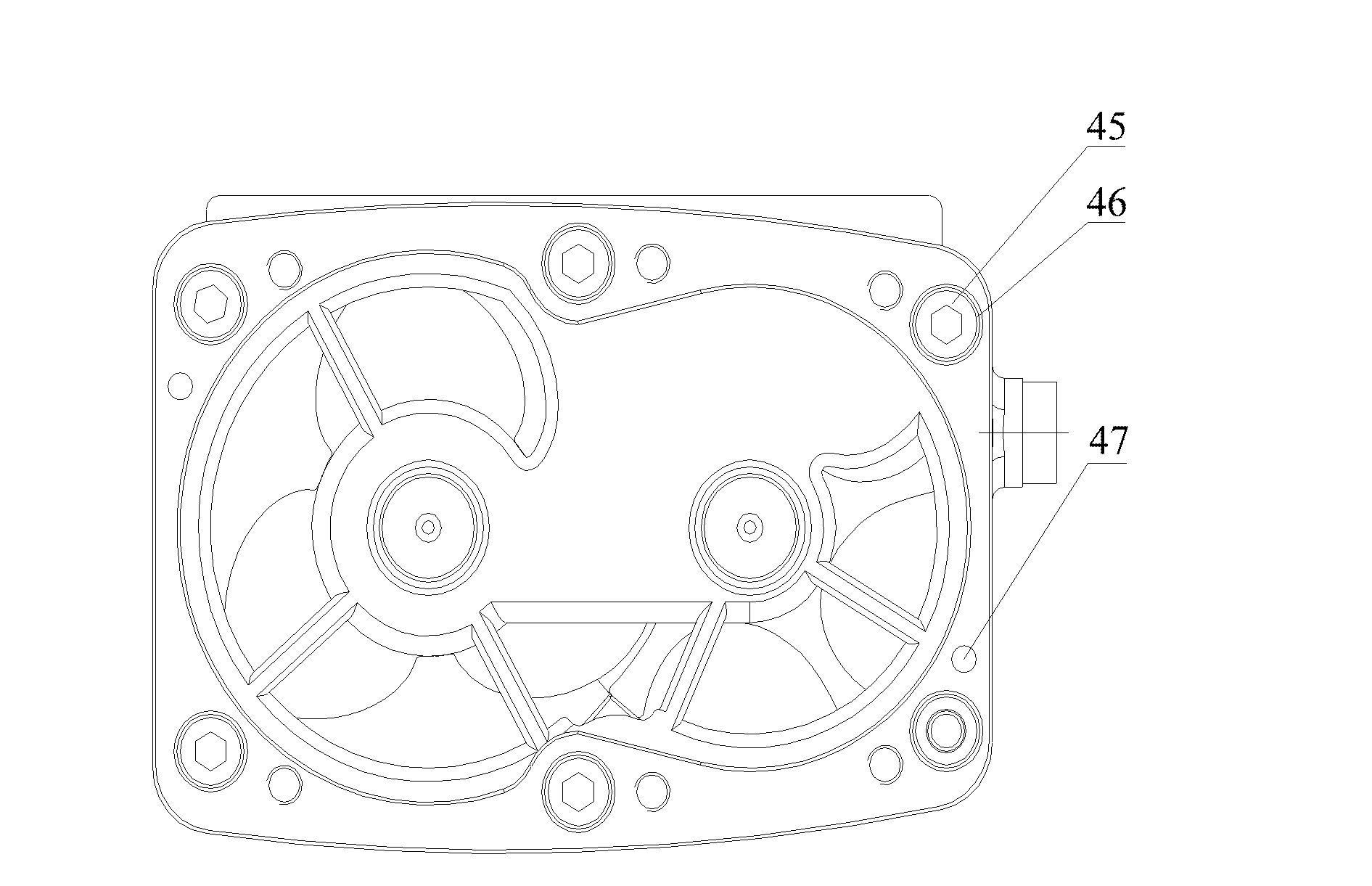
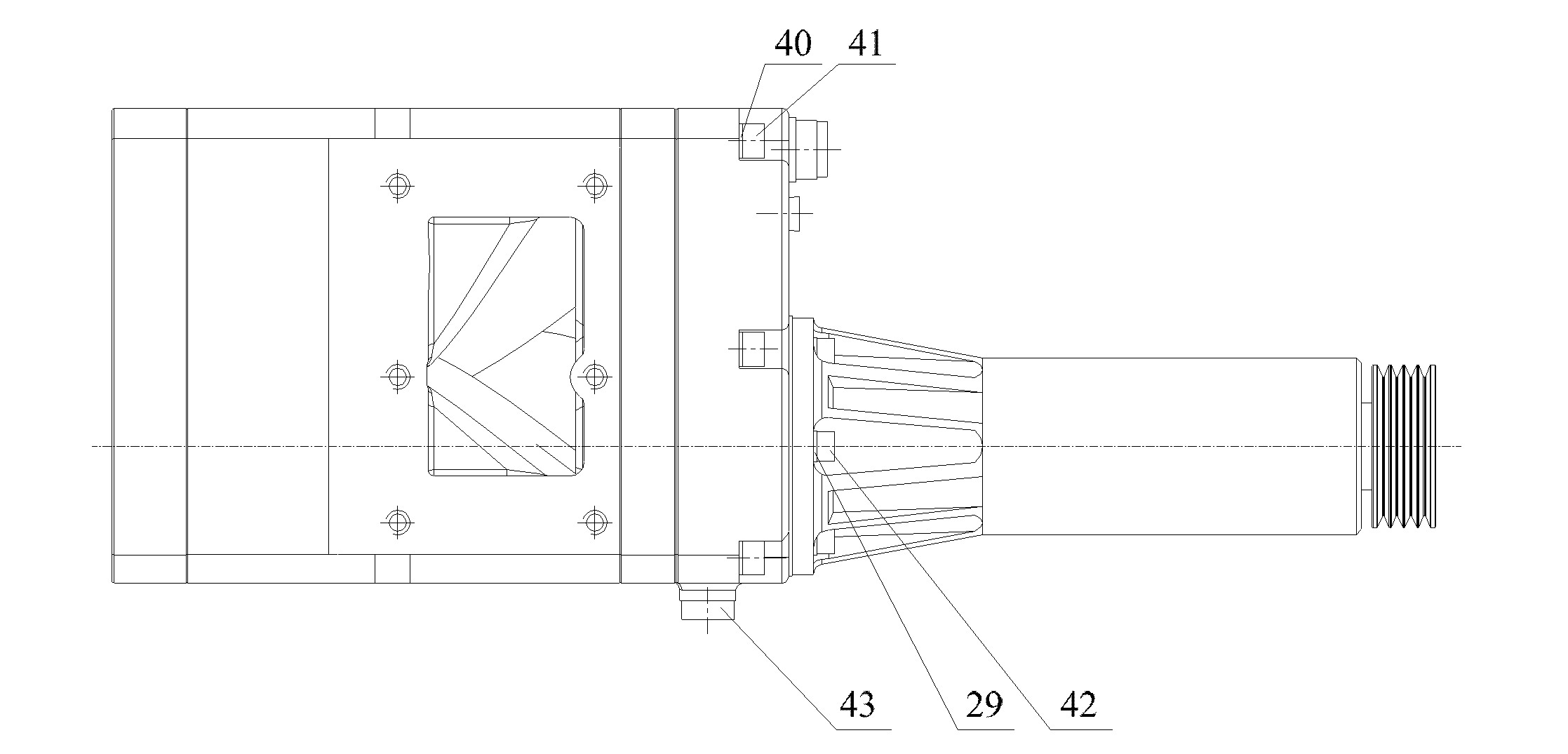
[0041] Please refer to Figure 1 to Figure 3 , figure 1 A schematic cross-sectional view of the overall structure of the oil-free twin-screw compressor provided by the embodiment of the present invention; figure 2 Schematic diagram of the installation structure of the oil-free twin-screw compressor inlet cover provided by the embodiment of the present invention; image 3 It is a schematic diagram of the installation structure of the transmission sleeve of t...


PUM


Abstract

The invention discloses an oil-free double-screw compressor. A male rotor is coaxially fixedly provided with a first axis embedding member and a female rotor is coaxially fixedly provided with a second axis embedding member; the first axis embedding member and the second axis embedding member are pivoted on a bearing block and are movably sealed together with the bearing block; the first axis embedding member and the second axis embedding member are hinged with an end cover of a synchromesh gear cavity; one end, which is located in the synchromesh gear cavity, of the first axis embedding member is fixedly connected with a small synchromesh gear; and one end, which is located in the synchromesh gear cavity, of the second axis embedding member is fixedly connected with a big synchromesh gear. Shaped line screw thread parts of the male rotor and female rotor of the oil-free double-screw compressor are manufactured from certain special materials which do not need to be subjected to heat treatment or certain special materials which are machined by other means difficult to deform, and the second axis embedding member of the female rotor and the first axis embedding member of the male rotor are manufactured from materials which meet the mechanical strength requirements, so that the machining difficulty of the male rotor and the female rotor is reduced when the special materials are used, and the application range of the oil-free double-screw compressor is widened.

Description

technical field [0001] The invention relates to the technical field of manufacturing screw compressors, in particular to an oil-free twin-screw compressor. Background technique [0002] In the existing market, twin-screw compressors are generally divided into oil-injected screw compressors and oil-free screw compressors. [0003] The oil-injected screw compressor is an oil-injected single-stage twin-screw compressor, which is driven by a high-efficiency pulley (or coupling) to drive the main engine to rotate to compress the air; the working process of the oil-injected screw compressor In the process, the oil is sprayed into the rotor chamber to realize the sealing between the male rotor and the female rotor and the sealing between the male rotor and the female rotor and the inner wall of the rotor chamber; in addition, the oil can also protect the air caused by air compression. It can also be used to lubricate the internal parts of the oil-injected screw compressor; finally...

Claims


Application Information

Patent Timeline
Patent Type & Authority Applications(China)
IPC IPC(8): F04C18/16
Inventor 吕志辉何志龙曾宪龙邢子文
Owner 江西隆恒科技有限公司
Why Eureka
Try Eureka