Supercharge Your Innovation With Domain-Expert AI Agents!

Position detection device

A detection device and magnetic detection technology, which is applied in the direction of using electric/magnetic devices to transmit sensing components, etc., can solve the problems of small detection output slope, slow magnetic field change, small magnetic flux density, etc., and achieve the improvement of position detection accuracy and timing. The effect of reduced delay

Inactive Publication Date: 2012-02-15
TOKYO COSMOS ELECTRIC CO LTD
View PDF7 Cites 5 Cited by
  • Summary
  • Abstract
  • Description
  • Claims
  • Application Information

AI Technical Summary

Problems solved by technology

[0005] exist Figure 10A , In the prior art of 10B and 10C, because the magnetic flux density near the boundary of the adjacent magnet plates is small, the change of the magnetic field becomes slow when the magnetic sensor moves relatively from the magnet plate on one side to the magnet plate on the other side, and as a result Yes, the slope of the rising edge and falling edge of the detection output of the magnetic sensor is small, and the hysteresis width of the position detection signal obtained by logically judging the detection output of the magnetic sensor through the threshold becomes large, resulting in a delay in the position detection timing, and it is difficult Improvement of rotation angle detection accuracy

Method used


Image

  • Position detection device
  • Position detection device
  • Position detection device

Examples


no. 1 example

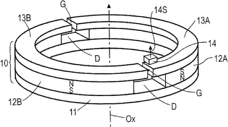
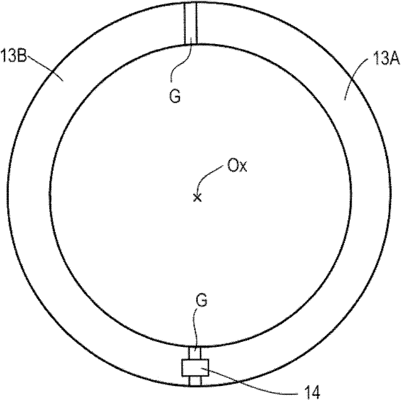
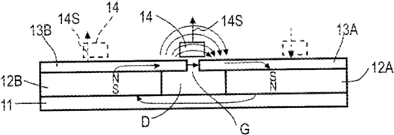
[0023] Figure 1A is a perspective view showing a magnetic detection type position detection device according to a first embodiment of the present invention, Figure 1B is its top view, Figure 1C Indicates a side view. In this embodiment, the rotating body 10 is composed of the following components, that is, a ring-shaped magnetic substrate 11, and an even number (two in this example) of arc-shaped magnet plates arranged in a circumferential direction on the surface of the magnetic substrate. 12A, 12B, and an even number of arc-shaped yoke plates 13A, 13B stacked on each of the magnet plates. The position detection device includes: a rotating body 10 , and a magnetic sensor 14 provided so as to be relatively rotatable with a certain distance from the surface of the yoke plate.

[0024] The annular magnetic substrate 11 is made of soft magnetic material with high magnetic permeability such as permalloy or silicon steel plate. The arc-shaped magnet plates 12A, 12B are forme...

no. 2 example

[0039] Figure 5 It shows the second embodiment of the position detecting device of the present invention. In this embodiment, the ring-shaped magnetic substrate 11, the arc-shaped magnet plates 12A, 12B arranged on the same circumference, and the arc-shaped yoke plates 13A, 13B arranged on the same circumference are arranged on the same surface along the radial direction. The rotating body 10 is formed by stacking in order from the inner side to the outer side. These magnetic substrate 11, magnet plates 12A, 12B, and yoke plates 13A, 13B have the same thickness in the direction of the rotation axis Ox.

[0040] The arcuate magnet plates 12A, 12B are magnetized radially in the stacking direction in this embodiment, and the magnetization directions of adjacent magnet plates are opposite in polarity in the radial direction. As in the first embodiment, both end surfaces in the circumferential direction of the respective magnet plates 12A, 12B are opposed to one end surfaces of ...

no. 3 example

[0043] Image 6 A position detecting device according to a third embodiment of the present invention is shown. This embodiment has a structure in which the ring of the annular rotating body 10 of the first embodiment is cut and extended in a linear direction. Therefore, the magnetic substrate 11 extends like a linear guide plate, and the magnet plate and the yoke plate thereon are formed in a rectangular shape. In order to set at least two gaps G, more than three desired magnet plates 12A, 12B, 12C, 12D... are provided, and yoke plates 13A, 13B, 13C, 13D having the same number as the magnet plates are provided. ... The magnetic substrate 11, the magnet plates 12A, 12B, 12C, and 12D, and the yoke plates 13A, 13B, 13C, and 13D are stacked integrally to form a rectilinear body 10'. The rectilinear body 10' is mounted on a linear movable part of a position detection object not shown in the figure so that the moving direction of the linear movable part coincides with the longitu...


PUM


Abstract

The invention relates to a position detection device. Arc-shaped magnet boards (12A, 12B) in even numbers are arranged on an annular magnetic substrate (11) with distance (D) separated, magnetic yoke boards (13A, 13B) are respectively laminated on the magnet boards (12A, 12B), a gap (G) is formed between end faces of each two adjacent magnetic yoke boards, the gap (G) is smaller than the distance (D) and is arranged in the center of the periphery of the distance (D), each magnet board (12A, 12B) is magnetized along the thickness direction, and magnetization directions of opposite end faces of two adjacent magnet boards are different.

Description

technical field [0001] The present invention relates to a magnetic detection type position detection device used for position detection of rotating parts or linearly moving parts of automobiles or industrial machines. Background technique [0002] Conventionally, in the case of a magnetic encoder that detects a rotational angle position, as shown in Japanese Patent Application Laid-Open H06-88704 (Patent Document 1), a pair of magnetic sensors placed near a disc-shaped magnet is magnetized in multiple stages. The change in the direction of the magnetic field produced by the rotation of a disc-shaped magnet is detected. Figure 10A It is a plan view of the magnetic rotary encoder disclosed in Patent Document 1, and the reference numerals are changed from those in Patent Document 1. Figure 10B and 10C It is a perspective view and a side view for explanation made by the inventor of this application in order to make the structure and operation|movement of this magnetic rotary ...

Claims


Application Information

Patent Timeline
Patent Type & Authority Applications(China)
IPC IPC(8): G01D5/12
Inventor 市仓学
Owner TOKYO COSMOS ELECTRIC CO LTD
Features
  • R&D
  • Intellectual Property
  • Life Sciences
  • Materials
  • Tech Scout
  • Unparalleled Data Quality
  • Higher Quality Content
  • 60% Fewer Hallucinations
Learn More