Audio signal transfer device
An audio signal and switching device technology, applied in the electronic field, can solve the problems of increasing the cost of electronic equipment, increasing the volume of electronic equipment, low output power of low-impedance voice coil speaker interface, etc., to achieve reduced volume and low hardware cost , cost reduction effect
- Summary
- Abstract
- Description
- Claims
- Application Information
AI Technical Summary
Problems solved by technology
Method used
Image

Examples
no. 1 example
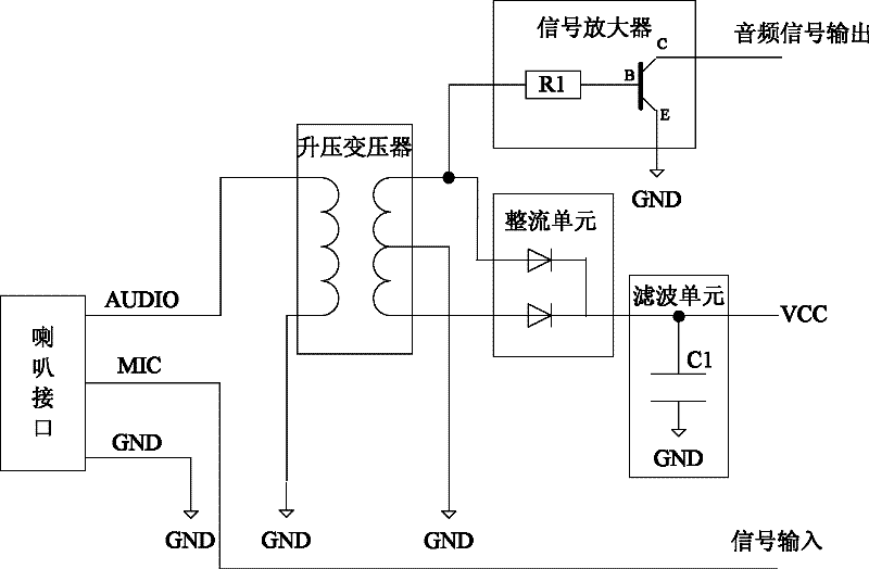
[0048] figure 1 It is a schematic structural diagram of the first embodiment of the audio signal switching device of the present invention; figure 1 As shown, the audio signal conversion device includes: a speaker interface, a booster unit (such as figure 1 Step-up transformer shown), rectifier unit, filter unit, power output pin (such as figure 1 VCC pin shown), the audio signal output pin; where:
[0049] The speaker interface is used for connecting with an audio signal sending device (for example, a mobile phone) and receiving an audio signal output by the audio signal sending device.
[0050] The above-mentioned speaker interface can be a low-impedance voice coil speaker interface (for example, a headphone interface), which includes: audio signal input pins (such as figure 1 AUDIO pin shown), ground pin (such as figure 1 GND pin shown).
[0051] In addition, the speaker interface may also include a microphone (MIC) pin, which is used to output a signal to an audio sig...
no. 2 example
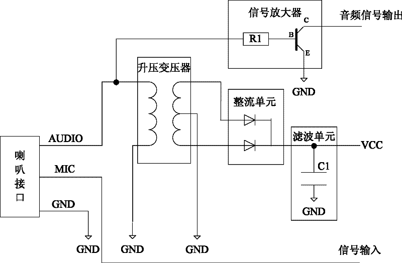
[0067] figure 2 It is a schematic structural diagram of the second embodiment of the audio signal switching device of the present invention; figure 2 As shown, the difference between the second embodiment of the present invention and the first embodiment is:
[0068] The audio signal output pin is connected with the audio signal input pin of the speaker interface.
[0069] Optionally, a signal amplifier may also be included between the audio signal output pin and the audio signal input pin of the speaker interface, that is, the input end of the signal amplifier is connected to the audio signal input pin, and the output end of the signal amplifier is used as the audio signal output pin. Pin (or connected to the audio signal output pin), output the amplified audio signal.
no. 3 example
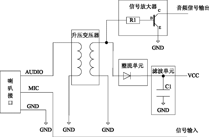
[0071] image 3 It is a schematic structural diagram of the third embodiment of the audio signal switching device of the present invention; image 3 As shown, the difference between the third embodiment of the present invention and the first embodiment is:
[0072] In the third embodiment of the present invention, only one output pin of the secondary coil of the step-up transformer is connected to the input pin of the rectification unit, so the rectification unit only needs to include one input pin, and the rectification unit only needs to include one diode. Can.
[0073] Obviously, compared with the first embodiment, this embodiment will lose half of the electric energy of the secondary coil of the step-up transformer, but the circuit structure can be simplified and the hardware cost can be reduced.
[0074] In this embodiment, another output pin of the secondary coil of the step-up transformer is grounded, and the step-up transformer does not include taps.
PUM
 Abstract
Description
Claims
Application Information
 - Generate Ideas
- Intellectual Property
- Life Sciences
- Materials
- Tech Scout
- Unparalleled Data Quality
- Higher Quality Content
- 60% Fewer Hallucinations
Browse by: Latest US Patents, China's latest patents, Technical Efficacy Thesaurus, Application Domain, Technology Topic, Popular Technical Reports.
© 2025 PatSnap. All rights reserved.Legal|Privacy policy|Modern Slavery Act Transparency Statement|Sitemap|About US| Contact US: help@patsnap.com