Rivet joint, auxiliary rivet joint and method for stress wave mounting of interference fit fastener

A riveting head and fastener technology, applied in the field of riveting devices, can solve problems such as easy deformation, and achieve the effect of avoiding deformation

Inactive Publication Date: 2012-02-22
NORTHWESTERN POLYTECHNICAL UNIV
View PDF10 Cites 13 Cited by
  • Summary
  • Abstract
  • Description
  • Claims
  • Application Information

AI Technical Summary

Problems solved by technology

[0004] In order to overcome the disadvantage that the existing stress wave installer is easy to deform the structure of the riveted part when the stress wave insta...

Method used


Image

  • Rivet joint, auxiliary rivet joint and method for stress wave mounting of interference fit fastener
  • Rivet joint, auxiliary rivet joint and method for stress wave mounting of interference fit fastener
  • Rivet joint, auxiliary rivet joint and method for stress wave mounting of interference fit fastener

Examples


Embodiment Construction

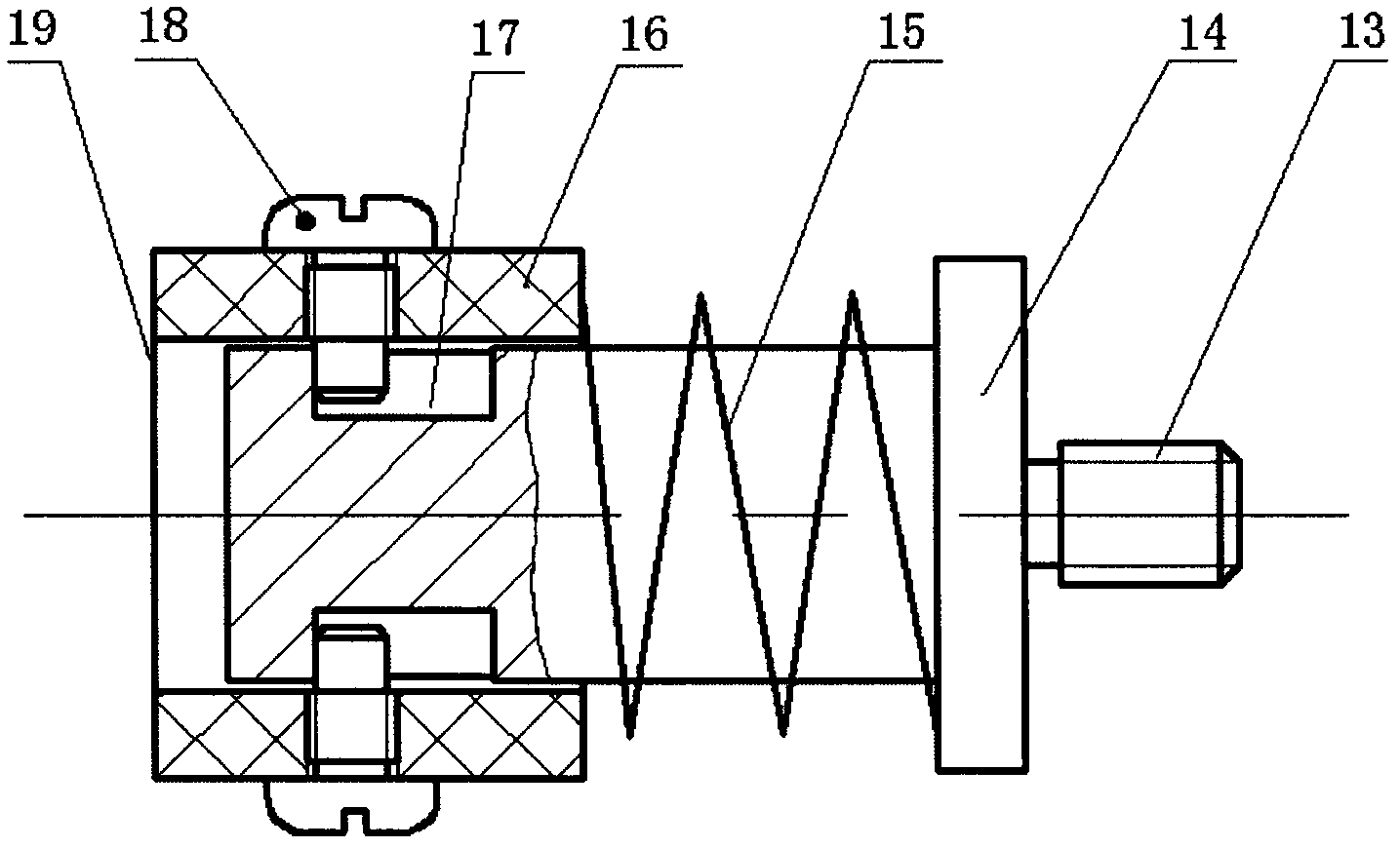
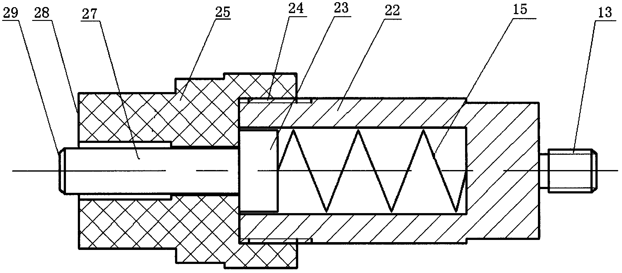
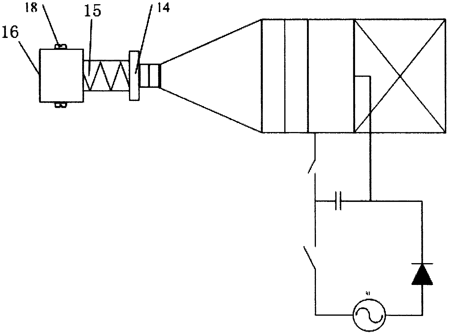
[0019] Reference Figure 1~5 . The riveting joint of the present invention includes a mandrel 14, a spring 15, a limiting cylinder 16 and a screw 18. The mandrel 14 is a piston-like structure. One end of the mandrel 14 is close to the radial position of the head and two key grooves 17 are symmetrically designed. The other end of 14 is a boss structure. The boss of the mandrel 14 is fixedly connected with a connector 13 and the connector 13 has threads; the mandrel 14 and the connector 13 are concentric. The limiting cylinder 16 is a cylindrical structure, which is sleeved on the end of the mandrel 14 close to the head. The mandrel 14 can move in the limiting cylinder 16, and the corresponding positions of the limiting cylinder 16 and the keyway 17 on the mandrel 14 have screw holes. , The screw 18 passes through the screw hole and extends into the keyway 17. The spring 15 is a compression spring, wound on the spindle 14, and located between the limiting cylinder 16 and the bos...


PUM


Abstract

The invention discloses a rivet joint, an auxiliary rivet joint and a method for stress wave mounting of an interference fit fastener, which are used for solving the technical problem that the structure of a riveted piece is prone to deformation when an existing stress wave mounting device is used for stress wave mounting of the interference fit fastener. The technical scheme is as follows: the rivet joint and the auxiliary rivet joint are respectively mounted on two electromagnetic riveting guns through connectors 13, and position-limiting and guide structures are respectively arranged on the rivet joint and the auxiliary rivet joint, thereby ensuring the alignment between the electromagnetic rivet guns and the fastener. The rivet joint and the auxiliary rivet joint can apply force on the two surfaces of the riveted piece, thereby avoiding the deformation of the riveted piece when the single electromagnetic rivet gun is used for applying the force on the single surface of the riveted piece.

Description

Technical field [0001] The invention relates to a riveting device, in particular to a riveting joint; also relates to an auxiliary riveting joint; and also relates to a method for installing interference fitting fasteners by stress waves by using the cooperation of the riveting joint and the auxiliary riveting joint. Background technique [0002] In the field of aviation manufacturing, interference fit connection can double the fatigue life of joints and is an important part of advanced aircraft manufacturing technology. However, the installation method of the interference fit fasteners driven by the pneumatic riveting gun, which is commonly used in production, can only achieve the installation of fasteners with a lower interference amount or a smaller diameter, and cannot achieve the best fatigue life gain. [0003] Reference Image 6 . The document "Chinese Utility Model Patent with Announcement Number CN2901681" discloses a stress wave installer for interference fit fasteners. ...

Claims


Application Information

Patent Timeline
IPC IPC(8): B21J15/10
Inventor 曹增强张彦昭盛熙
Owner NORTHWESTERN POLYTECHNICAL UNIV
Why Eureka
Try Eureka