1300mm moving blade of final stage for full-rotary-speed steam turbine

A technology for steam turbines and moving blades, applied to machines/engines, supporting components of blades, mechanical equipment, etc., can solve the problems of not meeting economic requirements, large energy consumption, small exhaust area, etc., and achieve low vibration stress and high The effect of aerodynamic efficiency and large exhaust area

Active Publication Date: 2012-02-22
HARBIN TURBINE +1
View PDF10 Cites 11 Cited by
  • Summary
  • Abstract
  • Description
  • Claims
  • Application Information

AI Technical Summary

Problems solved by technology

[0003] The purpose of the present invention is to provide a 1300mm final-stage moving blade of a full-speed steam turbine to solve the problems that the existing full-speed steam turbine's final-stage moving blade has a small length, a small steam exhaust area, and large energy consumption, which cannot meet higher economic requirements.

Method used


Image

  • 1300mm moving blade of final stage for full-rotary-speed steam turbine
  • 1300mm moving blade of final stage for full-rotary-speed steam turbine
  • 1300mm moving blade of final stage for full-rotary-speed steam turbine

Examples


specific Embodiment approach 1

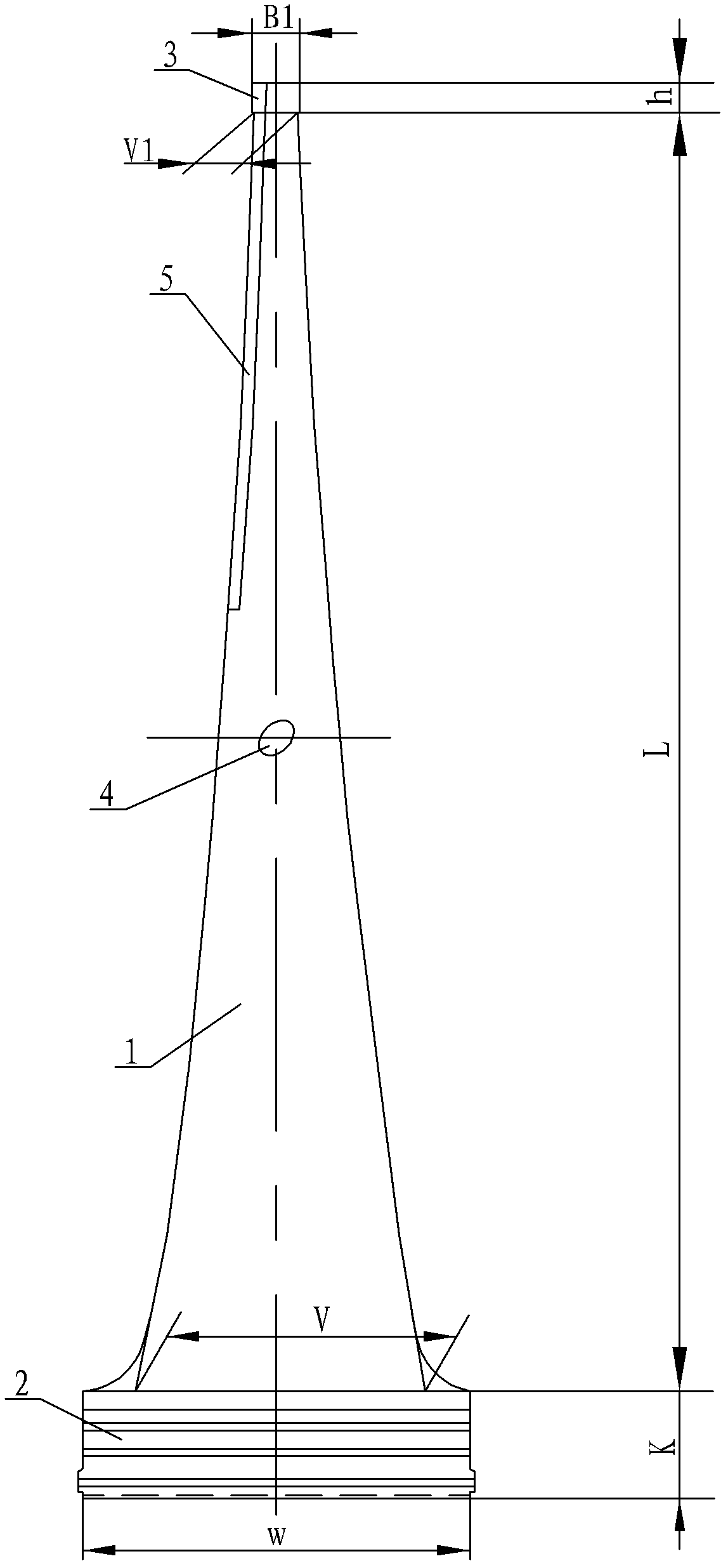
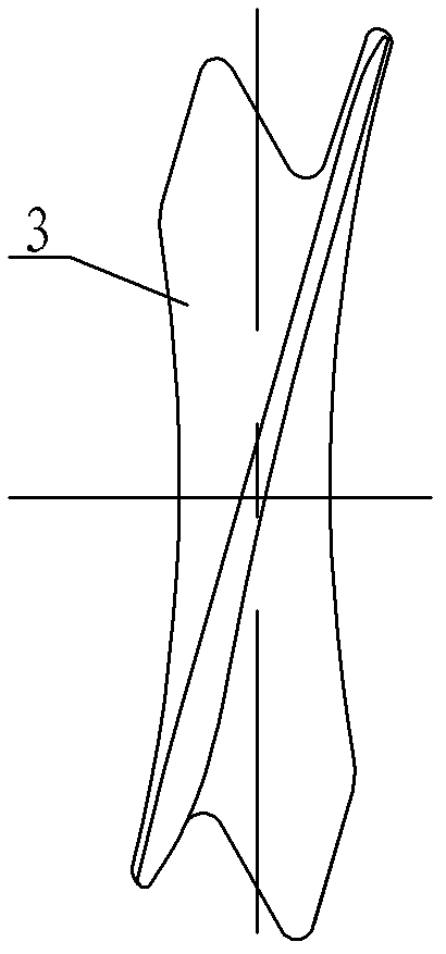
[0010] Specific implementation mode one: combine Figure 1 to Figure 5 Describe this embodiment, this embodiment is made up of blade working part 1, blade root 2, shroud 3, boss tie bar 4 and stellite alloy sheet 5, and shroud 3, blade working part 1 and blade root 2 are made up of Until the lower die is forged into one body, the boss tie bar 4 is located in the middle of the blade working part 1, and is made into one body with the blade working part 1. The profile line of the blade working part 1 is a variable-section twisted blade, that is, there is a gap between two adjacent sections. Relatively twisted, the cross-sectional area of ​​the blade working part 1 gradually decreases from the root to the top, and the upper air intake side of the blade working part 1 is pasted with a Stellite alloy sheet 5, which is used to prevent water erosion; the blade working part 1 The height L of the blade working part 1 is 1300mm, the axial width V of the root of the blade working part 1 i...

specific Embodiment approach 2

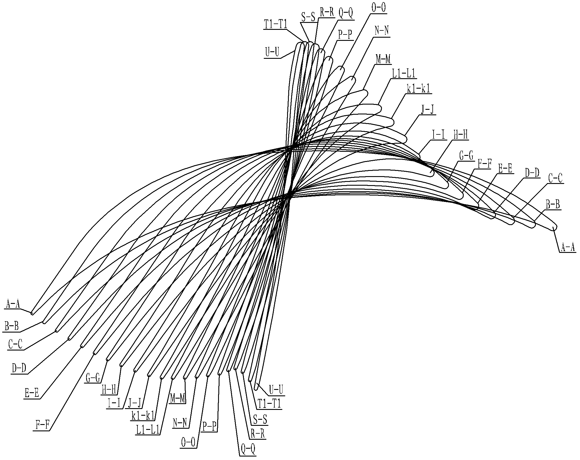
[0011] Specific implementation mode two: combination figure 1 , Figure 5 , Image 6 with Figure 7 To illustrate this embodiment, the variation range from the root axial width V of the blade working part 1 to the top axial width V1 of the blade working part 1 is 346.62 mm to 37.14 mm, and the variation range of the chord length b is 350.30 mm to 350.30 mm. 230.90mm, installation angle β y The range of change is 81.89°~8.87°, the range of maximum thickness T of mold line is 32.11mm~4.31mm, the range of change of inlet angle α is 55.51mm~167.35mm, the range of change of outlet angle θ is 40.47mm~15.37mm . By adopting the above structural parameters, the blades can be easily assembled while ensuring that the outer structure dimensions of the blades meet the design requirements. Other components and connections are the same as those in the first embodiment.

specific Embodiment approach 3

[0012] Specific implementation mode three: combination figure 1 , Figure 5 , Image 6 with Figure 7 To illustrate this embodiment, the height L of the blade working part 1 of this embodiment is 130 mm, 390 mm, 650 mm, 910 mm, and 1170 mm respectively, and the corresponding axial width V of the blade working part 1 is respectively: 303.20 mm, 227.07 mm, 156.87 mm mm, 94.39mm, 52.04mm, the corresponding chord length b is respectively: 310.51mm, 252.91mm, 228.87mm, 222.42mm, 222.73mm, and the corresponding installation angle β y They are respectively: 77.75°, 64.03°, 43.26°, 24.92°, 13.18°, and the corresponding maximum thickness T of the molding line is: 31.85mm, 28.05mm, 21.39mm, 9.62mm, 7.03mm respectively, and the corresponding import The angles α are respectively: 53.08°, 56.35°, 86.29°, 144.15°, 167.33°, and the corresponding outlet angles θ are respectively: 39.89°, 37.02°, 32.63°, 26.52°, 19.61°. By adopting the above structural parameters, the blades can be easily ...


PUM


Abstract

The invention discloses a 1300mm moving blade of the final stage for a full-rotary-speed steam turbine, and relates to a moving blade of the final stage for a full-rotary-speed steam turbine, and the moving blade is used for solving the problems of less length, small steam exhaust discharge area, great energy source consumption of the moving blade of the final stage for the full-rotary-speed steam turbine, and incapability of reaching higher economy requirement. A shroud, a blade operation part and a blade root are subjected to die forging integrally from top to bottom; a boss tie piece is positioned at the middle part of the blade operation part, and is integrated with the blade operation part; a stelite alloy sheet is sticked to the steam inlet side at the upper part of the blade operation part; the height of the blade operation part is 1300mm, the axial width of the root part is 346.62mm, the diameter of the root part is 1850mm, the steam exhaust area of the blade operation part is 12.86m<2>, and the axial width of the blade root is 400mm. The moving blade of the final stage provided by the invention is used for the full-rotary-speed steam turbine with the power between 600MW and 1000MW.

Description

technical field [0001] The invention relates to a last-stage moving blade used in a full-speed steam turbine. Background technique [0002] With the continuous demand for high-efficiency and energy-saving equipment in the power market, larger-capacity units require longer blades to improve the working efficiency and economy of the unit. Before the successful development of 1300mm blades, the steam passage height of the longest blades of the last-stage moving blades of full-speed steam turbines developed by other steam turbine manufacturers was not more than 1300mm, the exhaust area was small, and the energy consumption was large, which could not meet the demand for longer blades in the power market . Contents of the invention [0003] The purpose of the present invention is to provide a 1300mm final-stage moving blade of a full-speed steam turbine to solve the problems that the existing full-speed steam turbine's final-stage moving blade has a small length, a small steam ...

Claims


Application Information

Patent Timeline
Patent Type & Authority Applications(China)
IPC IPC(8): F01D5/14F01D5/30F01D5/26
Inventor 杨其国张秋鸿吕智强吴波管继伟杜连庆李宇峰张金春
Owner HARBIN TURBINE
Why Eureka
Try Eureka