A control method of high-power rlc AC electronic load

A technology of electronic load and control method, applied in the direction of output power conversion device, AC power input conversion to DC power output, electrical components, etc., can solve problems such as difficulty in satisfying simulation, steady-state waveform lag, and low dynamic response, and achieve The effect of reducing system cost, small steady-state phase shift, and simple hardware circuit topology

Active Publication Date: 2022-03-11
HEFEI KEWELL POWER SYST CO LTD
View PDF5 Cites 0 Cited by
  • Summary
  • Abstract
  • Description
  • Claims
  • Application Information

AI Technical Summary

Problems solved by technology

Therefore, hysteresis current control is also difficult to meet the simulation of AC electronic loads controlled by conventional IGBT low switching frequency.
[0005] Disadvantages of the prior art: (1) At present, in the analog AC electronic load industry, in order to obtain accurate simulation effects, high-speed switching devices such as MOSFETs and SICs are usually used as power devices, but the current capacity of such high-speed switching devices is low; ( 2) In order to meet the high-power test, it is necessary to use parallel tube or parallel machine to realize the simulation, which brings complicated control, low stability and high cost
Aiming at the characteristics of low dynamic response and lagging steady-state waveform of high-power RLC AC electronic load with IGBT as switching device due to low control frequency, this paper proposes a new method to improve the dynamic response of RLC AC electronic load and improve the steady-state waveform hysteresis

Method used


Image

  • A control method of high-power rlc AC electronic load
  • A control method of high-power rlc AC electronic load
  • A control method of high-power rlc AC electronic load

Examples


Embodiment 1

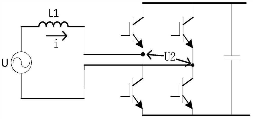
[0065] like figure 1 As shown, the main circuit of a high-power RLC AC electronic load includes an AC voltage source U, a filter inductor L1, an H-bridge circuit, and a controlled voltage source U2; the output of the AC voltage source U is connected to the H-bridge circuit through a filter inductor L1 The midpoint of the two bridge arms, the controlled voltage source U2 is the voltage output by the midpoint of the two bridge arms of the H bridge circuit, and the power switch tube of the H bridge circuit adopts IGBT.

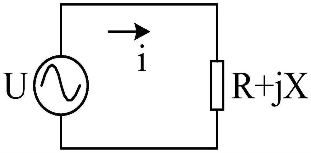
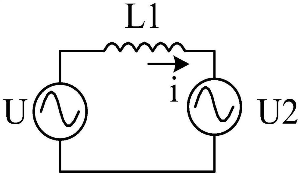
[0066] such as with figure 1 corresponding figure 2 and image 3 Shown, the RLC AC electronic load ideal model and actual model based on voltage control; The equivalent circuit of the RLC AC electronic load ideal model based on voltage control includes: AC voltage source U, analog load (R+jX load); The output end of the AC voltage source U is directly connected to the analog load to form a closed loop. The equivalent circuit of the actual model of the RLC ...


PUM


Abstract

A control method for a high-power RLC AC electronic load belongs to the field of power electronics technology for measurement and testing, and solves the problem of how to indirectly realize the current of the RLC circuit to be simulated by directly controlling the port voltage. By controlling the controlled voltage source in real time U2 realizes the simulation of RLC AC electronic load characteristics, and obtains the command voltage U2n+1 of the controlled voltage source U2 in the three modes of R, RC, and RL; the calculated voltage command U2n+1 is used as the command voltage of the H bridge, The output current characteristics of the RLC load to be simulated can be obtained by controlling the output voltage through the open-loop wave generation of the single voltage loop. Because the current is realized through the voltage difference, the dynamic response of direct voltage control is higher than that of direct current control. The RLC AC electronic load controlled by the method of the technical scheme of the invention has high dynamic response and small steady-state phase shift.

Description

technical field [0001] The invention belongs to the technical field of power electronics for measurement and testing, and in particular relates to a control method for a high-power RLC AC electronic load. Background technique [0002] RLC AC electronic load is a power electronic device that can simulate traditional impedance loads. It can simulate different values ​​of resistance, inductance, capacitance and their combinations. It can also simulate certain characteristics of nonlinear loads. Usually, AC electronic loads are controlled by input Current achieves the purpose of simulating various loads. Its original design is for the factory test of AC power supply or motor driver. Compared with the shortcomings of traditional real RLC devices, such as high energy consumption, low degree of automation, and inconvenient adjustment, the AC electronic load that simulates RLC characteristics can make the test easier and more flexible. , to reduce the test cost. [0003] At presen...

Claims


Application Information

Patent Timeline
Patent Type & Authority Patents(China)
IPC IPC(8): H02M7/219H02M1/12
CPCH02M7/219H02M1/126
Inventor 周玉柱张永董浩唐德平
Owner HEFEI KEWELL POWER SYST CO LTD
Why Eureka
Try Eureka