Piston type hydropneumatic buffer

A liquid-gas buffer, piston-type technology, used in shock absorbers, shock absorbers, springs/shock absorbers, etc., can solve the problems of reduced sealing difficulty, great sealing difficulty, and reduced buffer performance, and achieves a reduction in oil Possibility of vaporization, favorable for sealing, and improving the effect of dynamic sealing

Inactive Publication Date: 2012-02-22
吕再昌
View PDF3 Cites 25 Cited by
  • Summary
  • Abstract
  • Description
  • Claims
  • Application Information

AI Technical Summary

Problems solved by technology

When this plunger type liquid-gas buffer works, due to the formation of the third oil chamber 11 with low pressure, the difficulty of sealing is greatly reduced, compared with figure 1 The plunger-type liquid-gas buffer shown has a good sealing effect, but during the working process, the oil pressure in the third oil chamber fluctuates greatly, which is still not ideal; in addition, it is still impossible to avoid nitrogen leakage into the oil chamber, especially in the In the case of large impact, because the piston rod of the liquid-gas buffer has a larger diameter than the floating piston, when the piston rod moves under the impact, the moving stroke and speed of the floating piston will be larger, and the gas dynamic sealing under such conditions undertaken by the floating piston is very difficult. , resulting in increased leakage, when the nitrogen leaks to a certain extent, the buffer performance will decrease, or even fail

Method used


Image

  • Piston type hydropneumatic buffer
  • Piston type hydropneumatic buffer
  • Piston type hydropneumatic buffer

Examples


Embodiment Construction

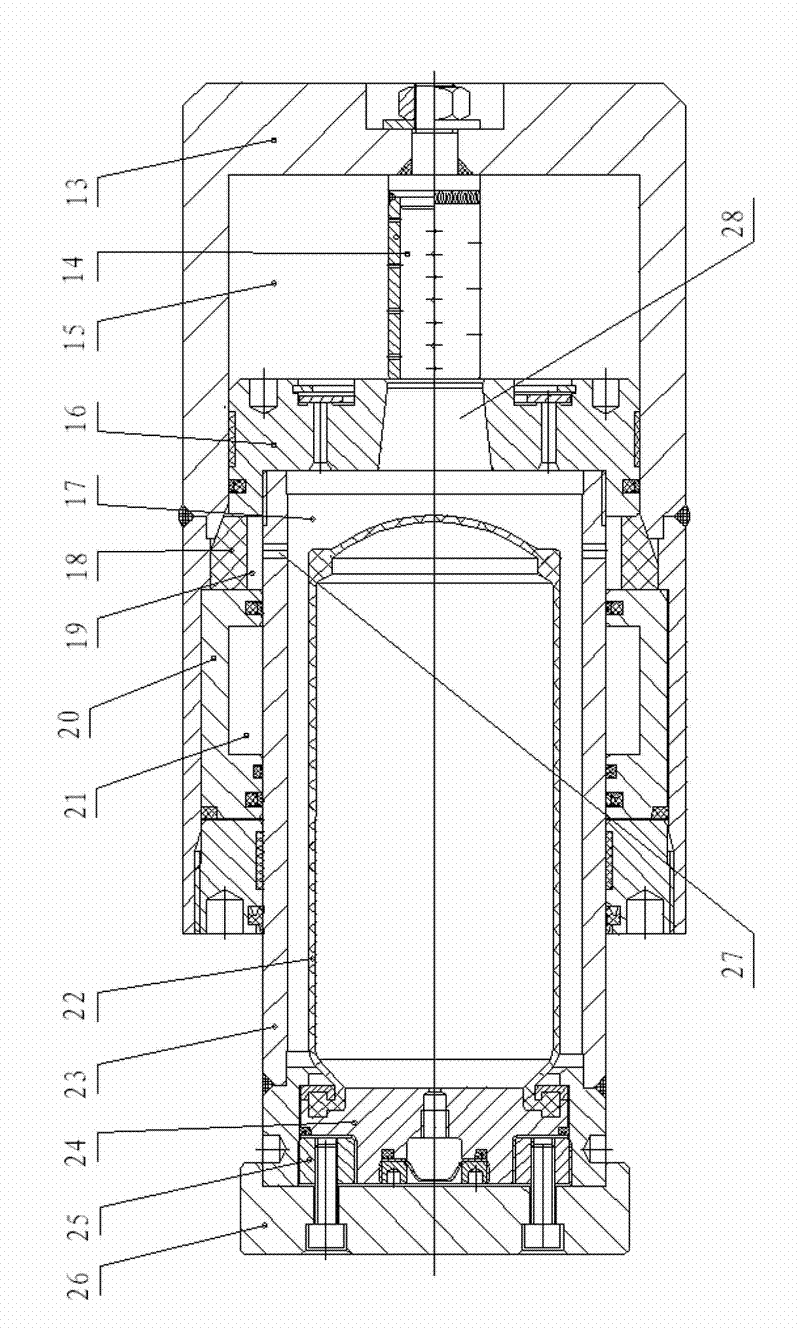
[0026] Such as image 3 As shown, the present invention is further described as follows:

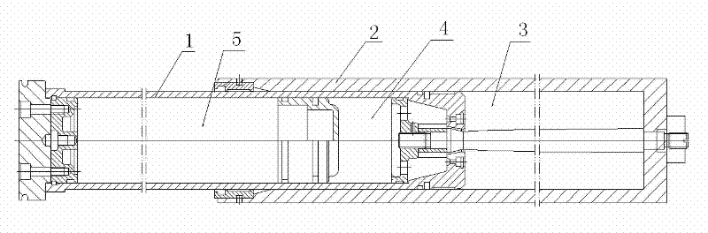
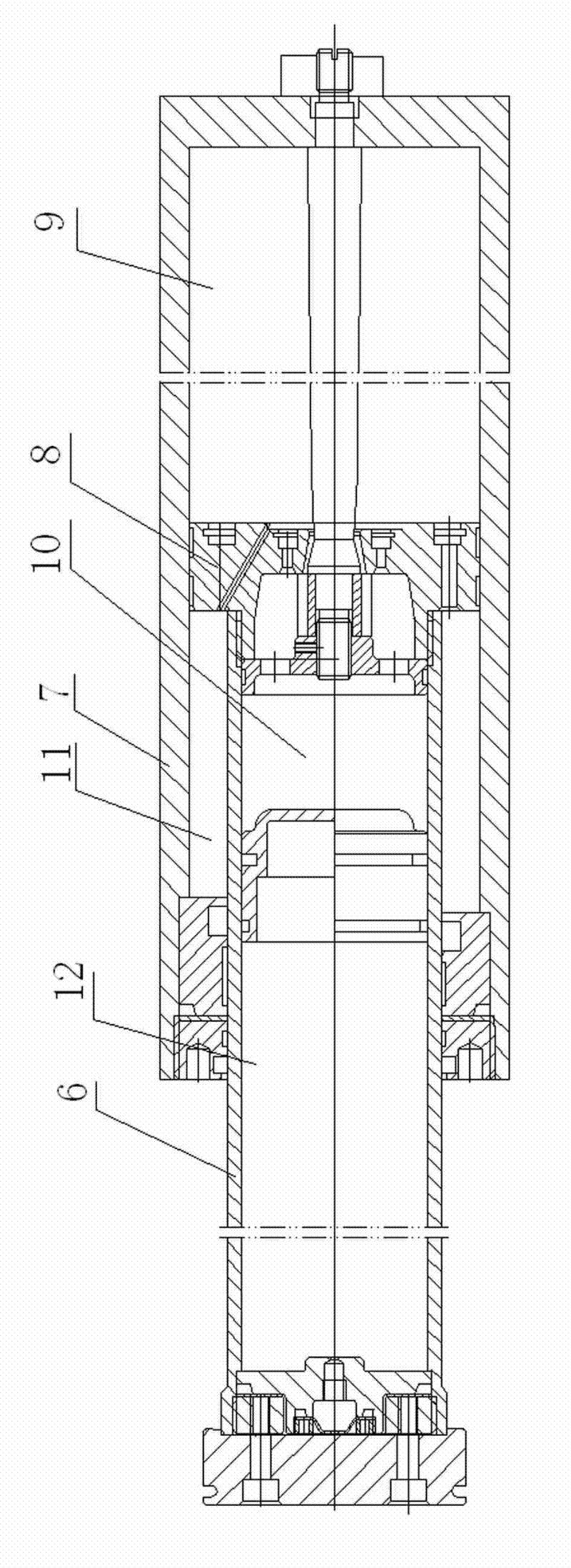
[0027] A piston-type liquid-gas buffer, comprising a cylinder 13, a hollow piston rod 23, and a piston 16, the inner end of the hollow piston rod 23 is fixedly connected to the piston 16, and a second end surface is formed between the inner end surface of the piston and the bottom of the cylinder body. An oil chamber 15, the air bag 22 is housed in the hollow piston rod, the air bag 22 is limited in the piston rod 23 by the plug 24 of its mouth, an airtight device is arranged outside the plug 24, the bottom of the air bag 22 and the piston There is a certain distance between the inner end surfaces of the rod 23, the second oil chamber 17 is formed between the air bag and the piston, and the first throttle passage is provided between the first oil chamber and the second oil chamber;

[0028] The cylinder body extends axially toward the head of the piston rod 23, forming a cavity between ...


PUM


Abstract

The invention provides a piston type hydropneumatic buffer which can be used for improving the sealing performance, maintaining the buffering performance and prolonging the service life. The technical scheme of the invention is as follows: the buffer comprises a cylinder body, a hollow piston rod and a piston fixedly connected with the piston rod, wherein a first oil cavity is formed between the bottom of the piston and the cylinder body, the piston rod is internally equipped with an air bag, an air tightness device is arranged outside a plug of the air bag, a second oil cavity is formed between the bottom of the air bag and the inner end face of the hollow piston rod, and a first throttling channel is arranged between the first oil cavity and the second oil cavity; a cavity is formed among the excircle of the piston rod, the outer end face of the piston and the cylinder body, a polyurethane limited block is arranged in the cavity, the outer end of the polyurethane limited block is provided with a guide seat which can partition the cavity into a third oil cavity and a fourth oil cavity, and a second throttling channel is arranged between the third oil cavity and the second oil cavity; and the first oil cavity, the second oil cavity and the third oil cavity are filled with low viscosity oil, the fourth oil cavity is filled with high viscosity oil and the air bag is filled with air.

Description

technical field [0001] The invention relates to a liquid-gas buffer. Background technique [0002] A variety of mobile machinery, such as cranes used in ports and construction sites, rail transport vehicles, rolling mills in the metallurgical industry, and elevators in high-rise buildings, are difficult to avoid collisions during work. In order to avoid the resulting huge load affecting the normal operation of the machine and the comfort of the occupants, and in order to avoid the resulting damage to the parts, various buffers are generally installed. [0003] Currently widely used buffers include rubber / polyurethane buffers and spring buffers with dry friction. These buffers are relatively simple in structure and easy to manufacture, but their capacity is small, energy consumption and heat dissipation are not good enough, and their performance is unstable. With the acceleration of people's production and life rhythm, the speed of vehicles or heavy loads, these buffers cann...

Claims


Application Information

Patent Timeline
Patent Type & Authority Applications(China)
IPC IPC(8): F16F9/088F16F9/34F16F9/36
Inventor 吕再昌
Owner 吕再昌
Why Eureka
Try Eureka