Speed reducer used for cooling tower

A technology for reducers and cooling towers, which is applied to components with teeth, transmission boxes, etc., can solve the problems of reducing the operating life of the reducer, complicated production and processing technology, and increasing processing costs, so as to increase operational reliability and safety. , reduce vibration and abnormal wear, and prolong the service life

Inactive Publication Date: 2012-02-22
南京大洋冷却塔股份有限公司
View PDF7 Cites 2 Cited by
  • Summary
  • Abstract
  • Description
  • Claims
  • Application Information

AI Technical Summary

Problems solved by technology

[0002]The housings of cooling tower reducers currently used are mostly combined assembly structures, and their structures are relatively complicated, because most of them are installed with the upper and lower housings, so that the upper and lower bearing seats are relatively The position is difficult to guarantee, especially the coaxiality of the center of the upper and lower bearing seats is difficult to control, which affects the accuracy of the center position of the main shaft of the reducer. In this working condition, the reducer is operated due to the inaccuracy of the center position of the main shaft. Eccentricity will greatly reduce the transmission efficiency, increase the running noise, accelerate the wear of the main shaft journal and bearing, and reduce the operating life of the reducer
In this case, generally in order to improve the centering performance of the upper and lower bearing seats, the accuracy of the fitting position of the assembly must be changed by improving the machining accuracy of the upper and lower shells. Therefore, the production and processing technology is complicated and the processing requirements are high. Will greatly increase the processing cost
At the same time, because it is a combined structure, during installation and maintenance, the position of the upper and lower bearing seats must be adjusted every time the main shaft is installed and adjusted, and the coaxiality of the center is aligned, which increases the difficulty and work of installation and maintenance. time
[0003] In addition, due to its combined structure, the sealing between the upper and lower housings has always been a long-term problem. If the sealing is not good, the lubricating grease will flow to the If there is no external leakage, gradually reduce the amount of lubricating grease, and the external water will enter the lubricating grease chamber, which will seriously affect the lubrication effect
Since the inner hole of the fan hub matches the output shaft end of the reducer as a cylinder; the inner hole of the V-belt pulley matches the input shaft end of the reducer as a cylinder, the above-mentioned matching is difficult to install on site and needs to be hammered , and when the reducer needs to be repaired and maintained, the fan hub needs to be pulled out by a puller. The workload is very heavy, and there are many tools. The above are the disadvantages of the current cooling tower reducer.

Method used


Image

  • Speed reducer used for cooling tower
  • Speed reducer used for cooling tower
  • Speed reducer used for cooling tower

Examples


Embodiment Construction

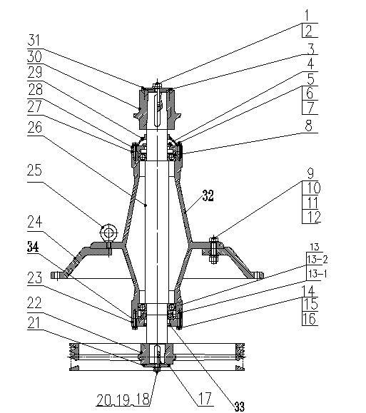
[0021] Such as figure 1 As shown, the cooling tower reducer according to the present invention includes a box body 32 , a base 24 and a drive shaft 26 . The base 24 is in the shape of a flange, and is provided with a lifting ring 17 for easy transportation, and forms a detachable connection with the box body 32 through the hexagonal bolt 9, the hexagonal nut 12, wherein between the hexagonal bolt and the box body 32, the hexagonal nut 12 A flat washer 10 and a spring washer 12 are arranged between the base 24 .

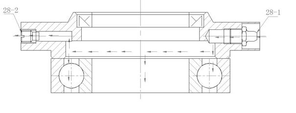
[0022] The top of the base 24 is used as the upper bearing seat, and the ball bearing 8 is installed inside. The upper end cover 28 for positioning the upper ball bearing 8 is fixed on the top of the box body 32 by the hexagonal bolt 5, and there is a gap between the hexagonal bolt 5 and the upper end cover 28. Spring washers 6 and flat washers 7 are provided. A water shield 29 is also provided on the top of the aforementioned upper end cover 28 , and the water shi...


PUM


Abstract

The invention relates to a speed reducer used for a cooling tower. The speed reducer used for the cooling tower comprises a box body, a base and a transmission main shaft, wherein the base is flange-shaped and is connected with the box body detachably; the top of the base serves as an upper bearing seat; a ball bearing is arranged in the upper bearing seat; the upper bearing seat is fixed by an upper end cover; the bottom of the base serves as a lower bearing seat; a lower bearing is arranged in the lower bearing seat; the lower bearing seat is fixed by a lower end cover; the transmission main shaft is installed and positioned in the box body of the speed reducer through the upper ball bearing and the lower bearing; and the upper end and the lower end of the transmission main shaft penetrate out of the box body, wherein the lower end of the transmission main shaft is connected with a V-belt pulley and the upper end of the transmission main shaft is connected with a fan hub. In the speed reducer used for the cooling tower, the box body, the upper bearing seat and the lower bearing seat are in an integrated casting structure, and the upper bearing seat and the lower bearing seat have very good coaxiality, so that the installation and the self-centering of the upper bearing and the lower bearing are facilitated; therefore, the accuracy of the center position of the main shaft of the speed reducer is ensured; vibration and abnormal abrasion caused by the eccentricity of the main shaft are reduced; and the safe and stable operation of the speed reducer is ensured.

Description

technical field [0001] The invention relates to a reducer for a cooling tower, in particular to a reducer transmitted by a belt. Background technique [0002] Most of the cooling tower reducer housings currently used are combined assembly structures, and their structures are relatively complicated, because most of them are installed in conjunction with the upper and lower housings, making it difficult to ensure the relative position of the upper and lower bearing seats, especially the coaxiality of the center of the upper and lower bearing seats. It is difficult to control, which affects the accuracy of the center position of the main shaft of the reducer. Running the reducer under this working condition will greatly reduce the transmission efficiency, increase the running noise, and accelerate the The wear of the main shaft journal and bearing will reduce the operating life of the reducer. In this case, generally in order to improve the centering performance of the upper a...

Claims


Application Information

Patent Timeline
Patent Type & Authority Applications(China)
IPC IPC(8): F16H57/02
Inventor 史金华费笑勇李晔昉卢香芹周雪英
Owner 南京大洋冷却塔股份有限公司
Why Eureka
Try Eureka