
Switch valve driven by magnetostrictive actuator

A magnetostrictive and giant magnetostrictive technology, applied in valve details, valve devices, engine components, etc., can solve the problems of low driving efficiency, poor control accuracy, poor reliability, etc., to achieve compact structure, reduce the number, reduce mechanical Effects of friction and clearance

Active Publication Date: 2012-02-22
BEIHANG UNIV
View PDF5 Cites 9 Cited by
  • Summary
  • Abstract
  • Description
  • Claims
  • Application Information

AI Technical Summary

Problems solved by technology

[0005] The purpose of the present invention is to provide a giant magnetostrictive high-speed digital switch valve with large displacement and high precision, so as to solve the problem of complex structure, poor reliability, large volume and power consumption of existing large displacement high-speed actuators matched with electro-hydraulic switch valves. High, low driving efficiency, and poor control accuracy

Method used


Image

  • Switch valve driven by magnetostrictive actuator
  • Switch valve driven by magnetostrictive actuator
  • Switch valve driven by magnetostrictive actuator

Examples


Embodiment Construction

[0064] The present invention will be further described in detail below in conjunction with the accompanying drawings.

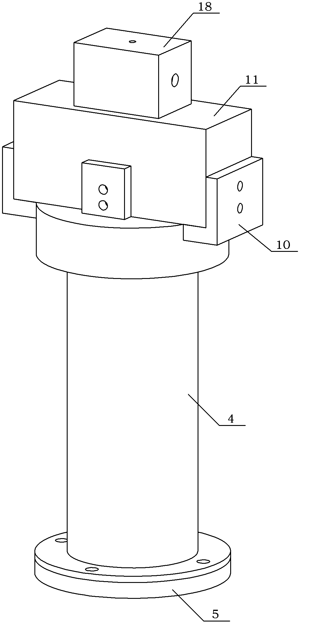
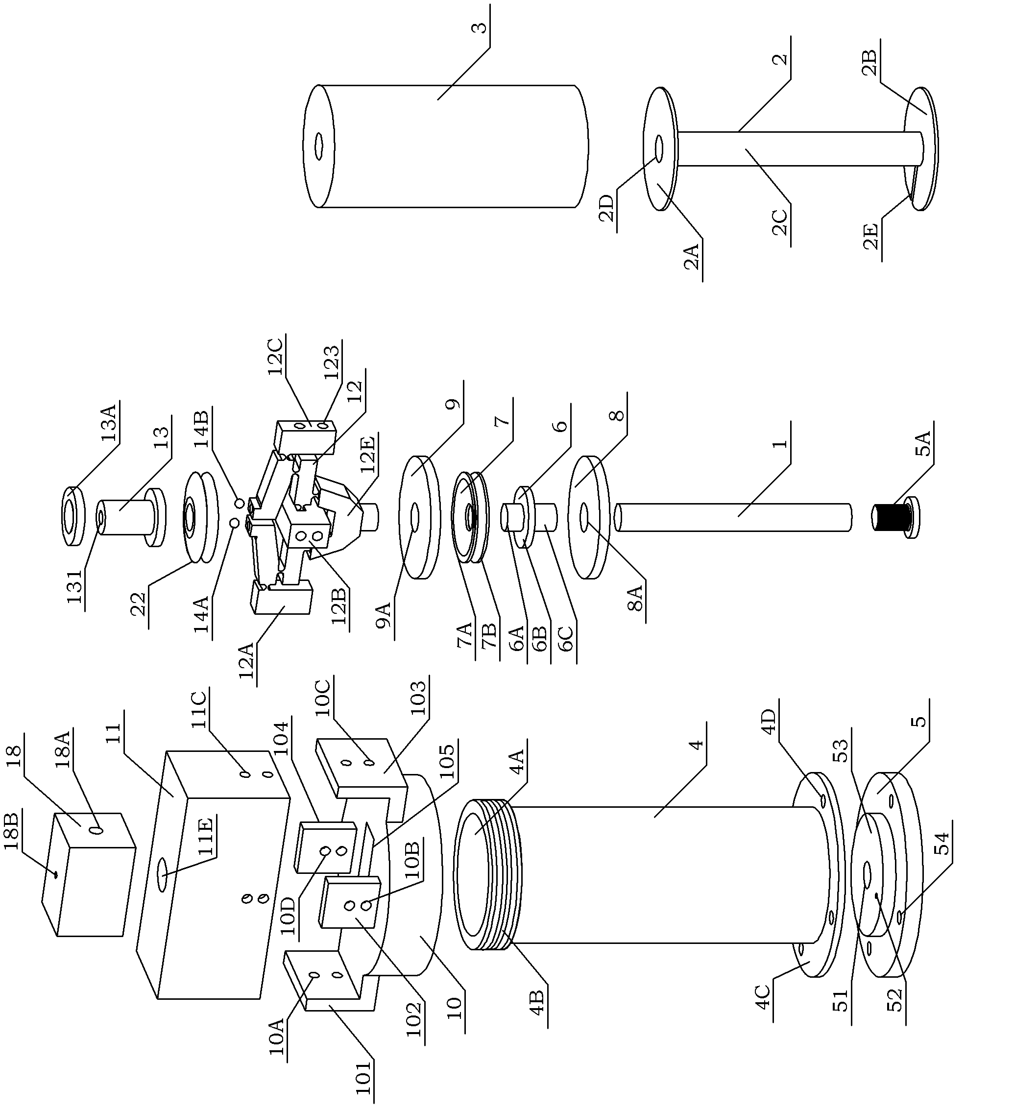
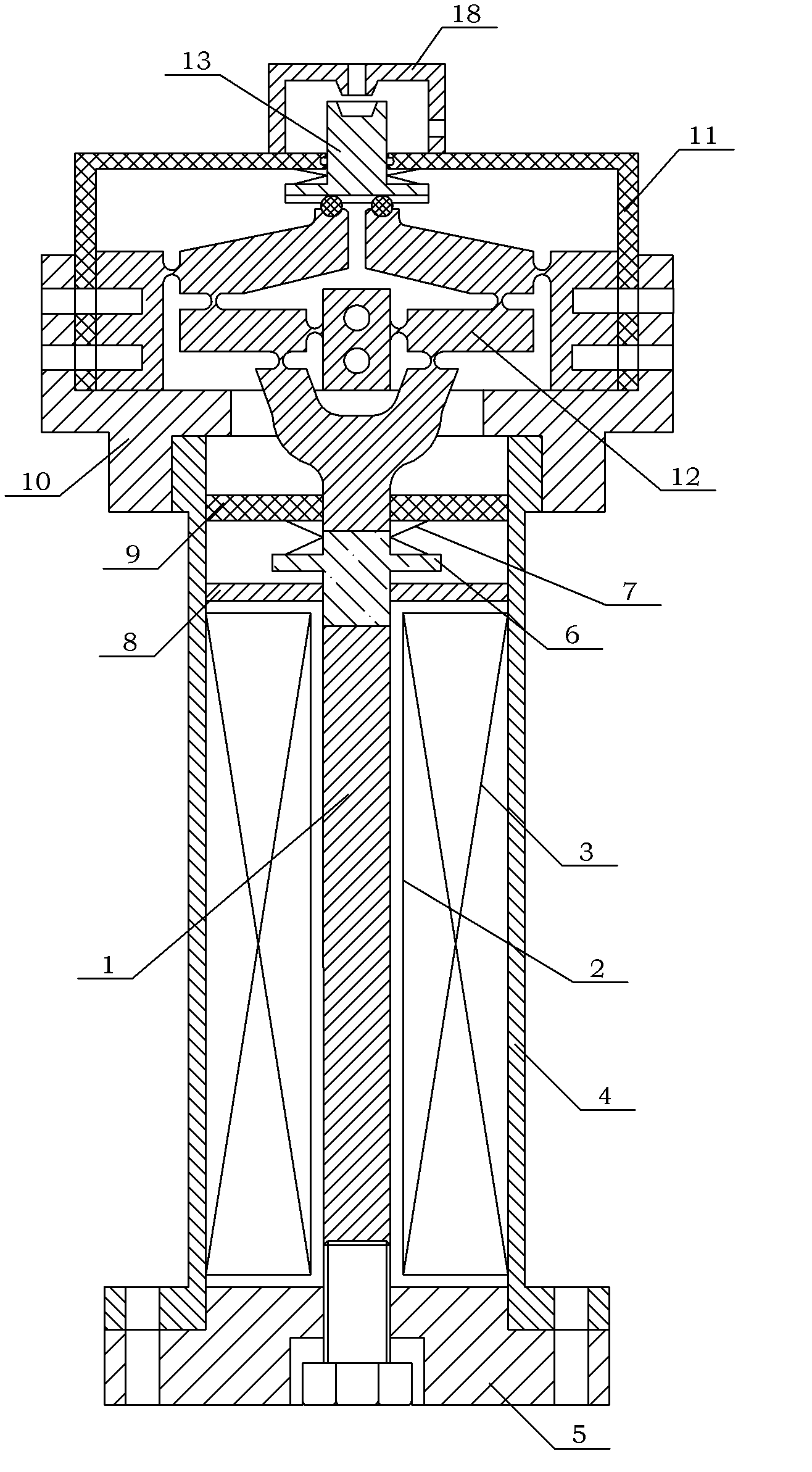
[0065] see figure 1 , Figure 1A , Figure 1B As shown, a switching valve driven by a magnetostrictive actuator of the present invention includes a giant magnetostrictive rod 1, a bobbin 2, an excitation coil 3, an outer sleeve 4, a chassis 5, a preload Bolt 5A, ejector rod 6, preload disc spring 7, return disc spring 19, limit plate 8, pressure plate 9, valve seat 10, valve housing 11, stroke amplifier 12, valve core 13, A ball shaft 14A, B ball Shaft 14B, valve body 18; wherein, giant magnetostrictive rod 1, coil bobbin 2 and excitation coil 3 form a drive unit; pre-compressed disc spring 7, reset disc spring 19, ejector rod 6, limit plate 8, pressure plate 9, The valve casing 11 , the stroke amplifier 12 , the valve core 13 , the A ball shaft 14A and the B ball shaft 14B form a transmission unit. The outer sleeve 4, the chassis 5, the pre-tightening bo...


PUM


Abstract

The invention discloses a switch valve driven by a magnetostrictive actuator, which is characterized in that a giant magnetostrictive rod in the switch valve is placed in a coil framework; an enamel wire is wound on the coil framework, and an outer sleeve is sleeved outside the coil framework; a chassis is mounted at the lower end of the outer sleeve, and a spacing disc is mounted at the upper end of the outer sleeve; a knockout pin is placed in an I-shaped through hole of the spacing disc; a pre-pressurized dish spring is sleeved on an upper guide post of the knockout pin; a pressure plate is pressed into the upper end of the outer sleeve and screwed into an E-shaped threaded hole of the chassis by pre-tightening force of a bolt; a thread boss of the outer sleeve is mounted in the threadcavity of a valve base, and a stroke column of a stroke amplifier is placed in a J-shaped through hole of the pressure plate; a ball journal is placed in a countersunk round hole of the stroke magnifier, and the ball journal moves in a guide track groove of a valve core; the valve core is mounted in a central through hole of a valve casing; the stroke magnifier, the valve casing and the valve base are installed by means of bolts; and the valve body is welded on the valve casing.

Description

technical field [0001] The invention relates to a high-speed on-off valve, more particularly to a high-precision, high-frequency-response magnetically controlled on-off valve driven by a giant magnetostrictive actuator with a displacement amplification mechanism. Background technique [0002] High-speed digital switching valve is a hydraulic component that can directly interface with computer digital input / output. Simple, strong anti-pollution ability and so on. The electronic control of fluid injection by high-speed valves depends on the pulse electromagnetic control valve, and the high-speed electromagnetic valve, as the direct interface between the system electronic control unit and the machine fluid injection device, directly controls the fluid injection process and plays an important role in various basic performances of the injection system. It plays a decisive role, which requires the valve drive device, that is, the actuator, to have basic characteristics such as fa...

Claims


Application Information

Patent Timeline
IPC IPC(8): F16K31/06
Inventor 张天丽张恒蒋成保徐惠彬
Owner BEIHANG UNIV
Learn More