Magnetic integrated double inductor

A dual-inductance, magnetic integration technology, applied in the field of inductors, can solve problems such as large circuits, and achieve the effect of suppressing the generation of high-order harmonics

Active Publication Date: 2012-02-22
TAMURA CORP OF CHINA LTD +1
View PDF6 Cites 10 Cited by
  • Summary
  • Abstract
  • Description
  • Claims
  • Application Information

AI Technical Summary

Problems solved by technology

In the conventional circuit, the inductors 101 and 102 are formed by using two separate inductance elements, which has the problem of increasing the size of the circuit.

Method used


Image

  • Magnetic integrated double inductor
  • Magnetic integrated double inductor
  • Magnetic integrated double inductor

Examples


Embodiment Construction

[0023] The inductance value of an inductor is usually described by the following formula:

[0024] L=μ 0 mu r N 2 A / l

[0025] Among them, L is the inductance, the unit Henry (H); μ 0 Permeability of free space = 4π*10 -7 H / m; μ r is the relative magnetic permeability of the core material; N is the number of turns; A is the cross-sectional area of ​​the surrounding, in square meters (m 2 ); l is the length of the coil, in meters (m).

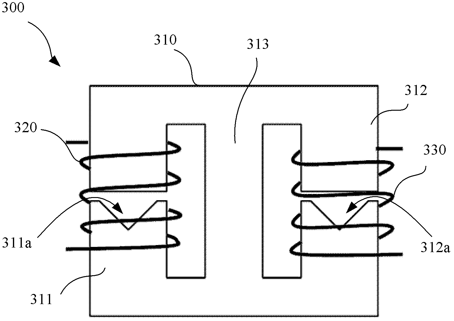
[0026] Due to the existence of the air gap in the inductor structure, the equivalent value of the relative permeability of the magnetic core material that determines the size of the inductance is greatly reduced, thereby making the inductance value smaller. According to this principle, if the core material with a smaller cross-sectional area is used in the air gap space of the air part, on the magnetic circuit inside the inductor coil, the same magnetic flux has to pass through the narrow core space, so that this part is small. area of ​...


PUM


Abstract

The invention relates to a magnetic integrated double inductor, which comprises two groups of coils and a magnetic core, wherein the magnetic core comprises two arms which are formed integrally and are used for the coils and at least one shared arm; a group of coils is wound on each arm for the coils; the shared arm and each arm for the coils form a magnetic flux ring; and an air gap is reserved on each arm for the coils, and the sectional area of a magnetic material for forming the air gaps is changed linearly along the arms for the coils.

Description

technical field [0001] The invention relates to an inductor, in particular to a magnetically integrated double inductor. Background technique [0002] Inductors are circuit elements that are often used in electrical circuits. In some occasions, it is necessary to use two inductors with exactly the same characteristics. by figure 1 For the shown interleaved PFC (Power Factor Correct, power factor correction) voltage conversion circuit 100, two inductors 101, 102 are connected in parallel to the circuit. This circuit requires that the characteristics of the inductors 101, 102 be identical. In a conventional circuit, the inductors 101 and 102 are respectively configured using two separate inductance elements, which has a problem of increasing the size of the circuit. [0003] In order to solve this problem, there has been proposed an inductor having a plurality of sets of coils, a magnetic core consisting of a plurality of coil arms respectively wound by a plurality of coil...

Claims


Application Information

Patent Timeline
IPC IPC(8): H01F37/00H01F27/30H02M1/42
CPCY02B70/10
Inventor 邵革良铃木敦梁志勇朱鸿江明
Owner TAMURA CORP OF CHINA LTD
Why Eureka
Try Eureka