
Gas current transformer

A current transformer and gas technology, applied in the field of transformers, can solve problems affecting product quality and safety performance, basin insulator insulation breakdown, shielding tube offset, etc., to achieve safe and reliable insulation performance, improved insulation reliability, The effect of ensuring the reliability of insulation

Inactive Publication Date: 2012-02-22
BAODING TIANWEI GRP CO LTD
View PDF5 Cites 4 Cited by
  • Summary
  • Abstract
  • Description
  • Claims
  • Application Information

AI Technical Summary

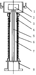
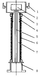
Problems solved by technology

[0002] In the background technology, 35-500kV inverted SF 6 A gas insulated current transformer generally consists of a primary conductor, a shell, a secondary winding shield, a secondary winding, a secondary winding lead wire shielding tube, a high potential shielding cylinder, a base, a porcelain sleeve (or a hollow composite insulator), an SF 6 Composed of gas, pot insulators, etc., the secondary winding lead wire shielding tube extends into the pot insulator, the upper end of the shielding tube is close to the pot insulator insulation distance, especially for products above 220kV, the shielding tube is very long and needs to lie down During transportation, the shielding tube is prone to deflection, which will cause insulation breakdown of the shielding tube to the pot insulator, affecting product quality and safety performance

Method used


Image

  • Gas current transformer
  • Gas current transformer
  • Gas current transformer

Examples


Embodiment Construction

[0011] The present invention will be further described through the embodiments below in conjunction with the accompanying drawings.

[0012] A gas current transformer, comprising a primary conductor 1, a secondary winding shield 2, a pot insulator 3, a high potential shielding cylinder 4, a secondary winding lead wire shielding tube 5, a hollow composite insulator 6, an SF 6 The gas 7 and the base 8, the primary conductor and the secondary winding shielding cover are set on the top, the bottom is the pot insulator, the high potential shielding cylinder, the secondary winding lead-out line shielding tube, the hollow composite insulator, and the secondary winding lead-out line shielding tube is set on In the hollow composite insulator, the hollow composite insulator is set on the base and filled with SF 6 The special feature is: the upper end of the secondary winding lead-out wire shielding tube is flush with the upper end of the pot insulator, and an insulating sleeve 9 is seal...


PUM


Abstract

The invention relates to a gas current transformer, in particular to an inverted SF6 (Sulfur Hexafluoride) gas insulated current transformer with a voltage of 35-500 kV, belonging to the technical field of a transformer. The technical scheme provided by the invention is as follows: the gas current transformer comprises a primary conductor (1), a shielding cover for a secondary winding (2), a disk-type insulator (3), a high-potential shielding cylinder (4), a shielding tube of a lead-out wire of the secondary winding (5), a compound hollow insulator (6), an SF6 gas (7), a base (8) and the like; the upper end of the shielding tube of the lead-out wire of the secondary winding is leveled and parallel to the upper end of the disk-type insulator; an insulating sleeve (9) is sealed and fixed on the upper end of the shielding tube of the lead-out wire of the secondary winding; and a gap is reserved between the insulating sleeve and the disk-type insulator. In the gas current transformer provided by the invention, the insulation reliability between the shielding tube of the lead-out wire of the secondary winding and the disk-type insulator is improved so that the insulation reliability of the transformer is ensured. Compared with the prior art, the gas current transformer provided by the invention has advantages of material saving, simple and novel structure, convenience for manufacture and installation, and safeness and reliability in the insulation performance.

Description

technical field [0001] The invention relates to a gas current transformer, especially a 35-500kV inverted SF 6 A gas-insulated current transformer belongs to the technical field of transformers. Background technique [0002] In the background technology, 35-500kV inverted SF 6 A gas insulated current transformer generally consists of a primary conductor, a casing, a secondary winding shield, a secondary winding, a secondary winding lead wire shielding tube, a high potential shielding cylinder, a base, a porcelain sleeve (or a hollow composite insulator), an SF 6 Composed of gas, pot insulators, etc., the secondary winding lead wire shielding tube extends into the pot insulator, the upper end of the shielding tube is relatively close to the pot insulator insulation distance, especially for products above 220kV, the shielding tube is very long and needs to lie down During transportation, the shielding tube is prone to deflection, which will cause insulation breakdown of the ...

Claims


Application Information

Patent Timeline
Patent Type & Authority Applications(China)
IPC IPC(8): H01F38/30H01F27/29H01F27/32
Inventor 张伟明薛晚道王文娣黄洁孙红萍孟令
Owner BAODING TIANWEI GRP CO LTD
Learn More